Tricky lean-to junctions

Good detailing of the roof wall junction for lean-tos is important for the weathertightness of a building, but this junction can present some challenges.

Topics include

Weathertightness
Last updated 19 May 2026
Share

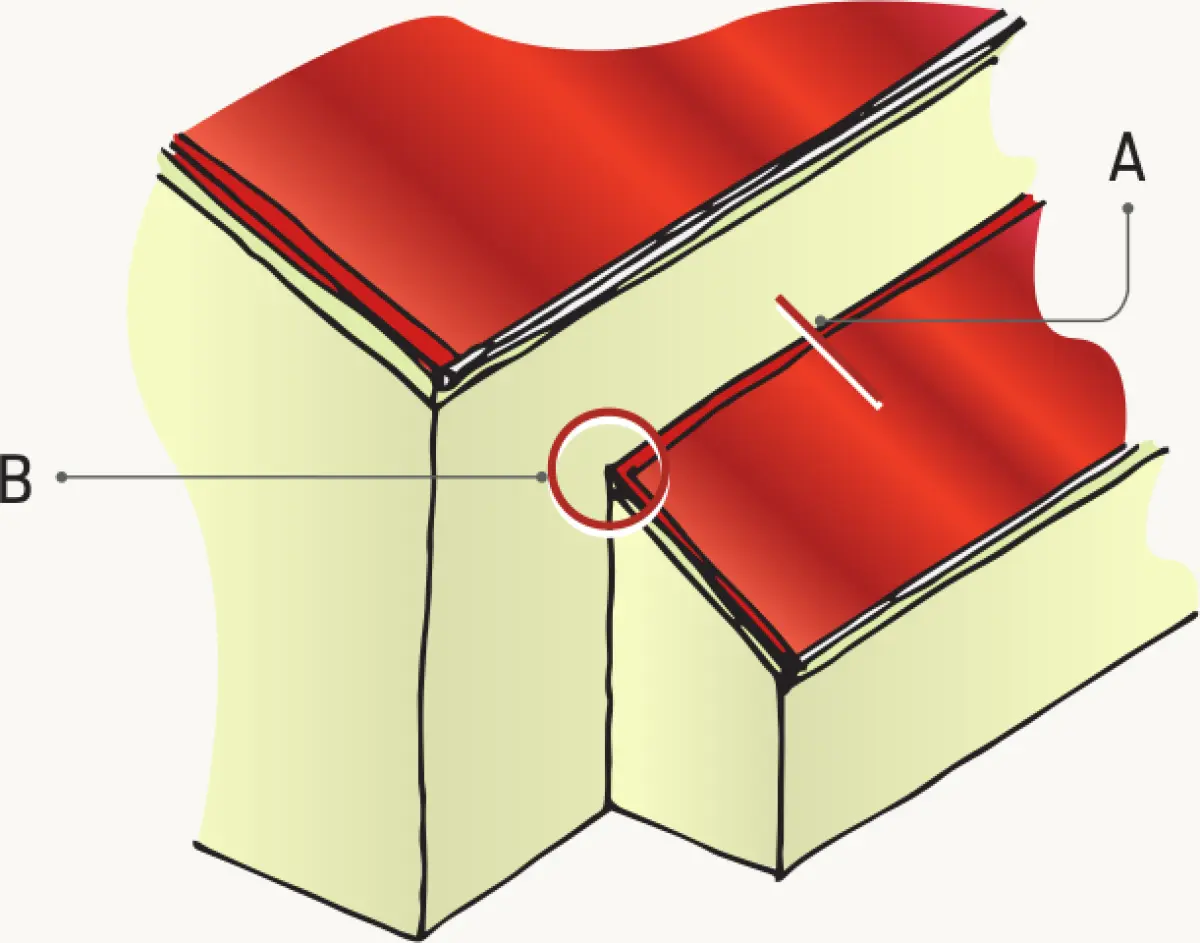
Roof wall junctions can be classed as simple, such as a standard horizontal apron flashing (see A in Figure 1), or complex, such as where the previous apron flashing terminated within the wall area (see B in Figure 1).

Detail A is covered by E2/AS1, but detail B is not.

Illustration showing two roof planes meeting at an inward corner, with a highlighted junction detail where the lower roof meets a vertical wall
Figure 1 Lean-to

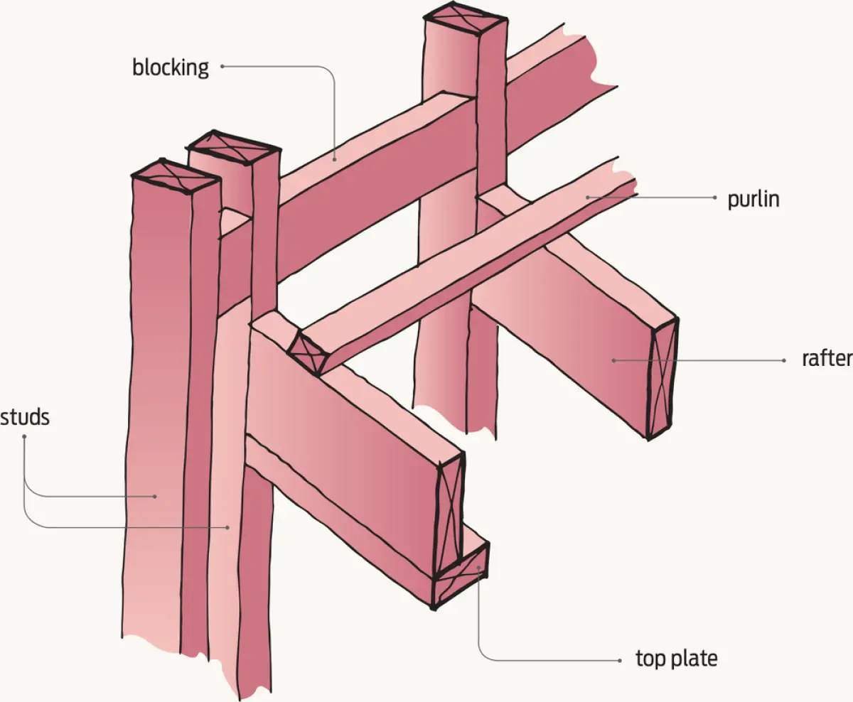
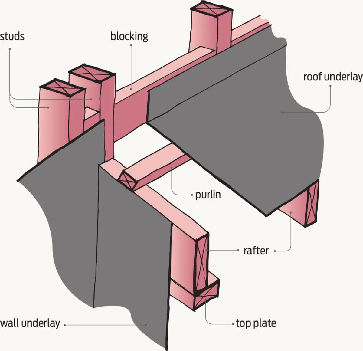
Building up the detail

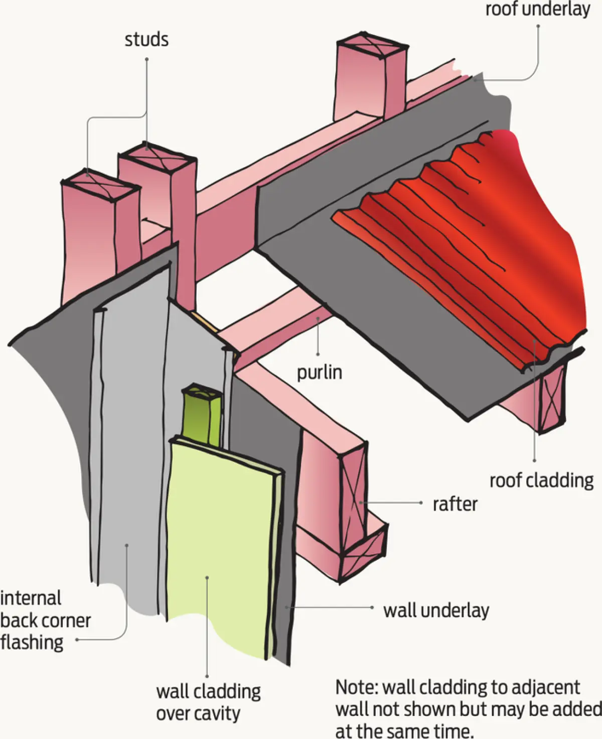
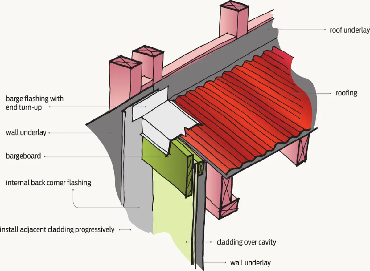
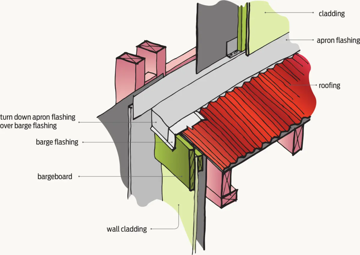
Key elements to address with the termination of the flashing at B are:

  • preventing wind-blown water getting under the edge of the flashing laid over the roof by downturning the end of the flashing cladding to the lean-to
  • back flashing the internal corner and ensuring the back flashing extends up behind the bargeboard and the apron flashing upstand.

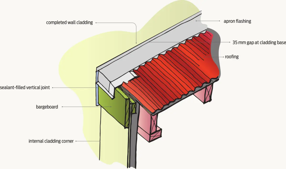
Figures 2–7 outline the construction sequence for one option for detailing this tricky junction.

Diagram showing timber wall studs and a top plate with roof rafters and a purlin connected by blocking
Figure 2 Construction sequence step 1 – Framing.
Diagram showing timber wall studs and roof framing, with dark wall underlay and roof underlay draped over the framing members
Figure 3 Step 2 – Wall and roof underlay.
Diagram showing timber wall framing with roof framing above, wall underlay, cavity‑fixed wall cladding, and roof cladding layered over roof underlay at a junction
Figure 4 Step 3 – Back flashing internal corner.
Diagram showing a roof edge and wall junction with profiled roofing above, wall cladding over a cavity below, and folded flashing details between the roof and wall
Figure 5 Step 4 – Installing barge flashing.
Diagram showing a roof‑to‑wall junction with profiled roofing above, wall cladding below, and layered flashing elements folded between the roof edge and the wall
Figure 6 Step 5 – Install apron flashing.
Diagram showing a completed roof‑to‑wall junction with profiled roofing above, finished wall cladding below, and an apron flashing folded between the roof edge and the wall
Figure 7 Step 6 – Completed detail.