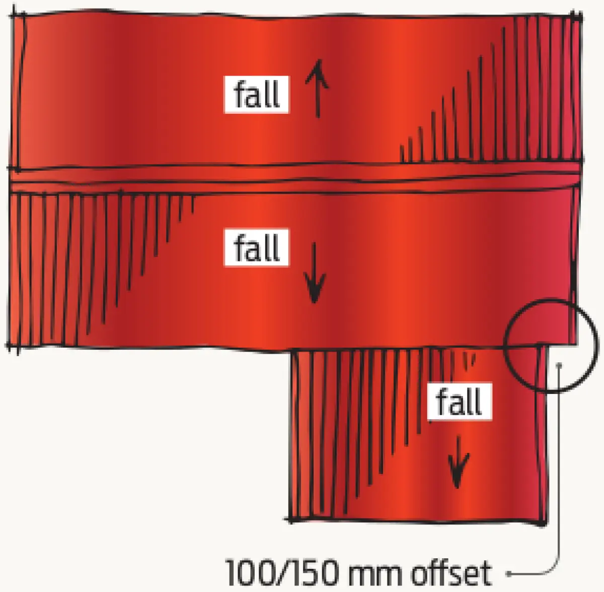


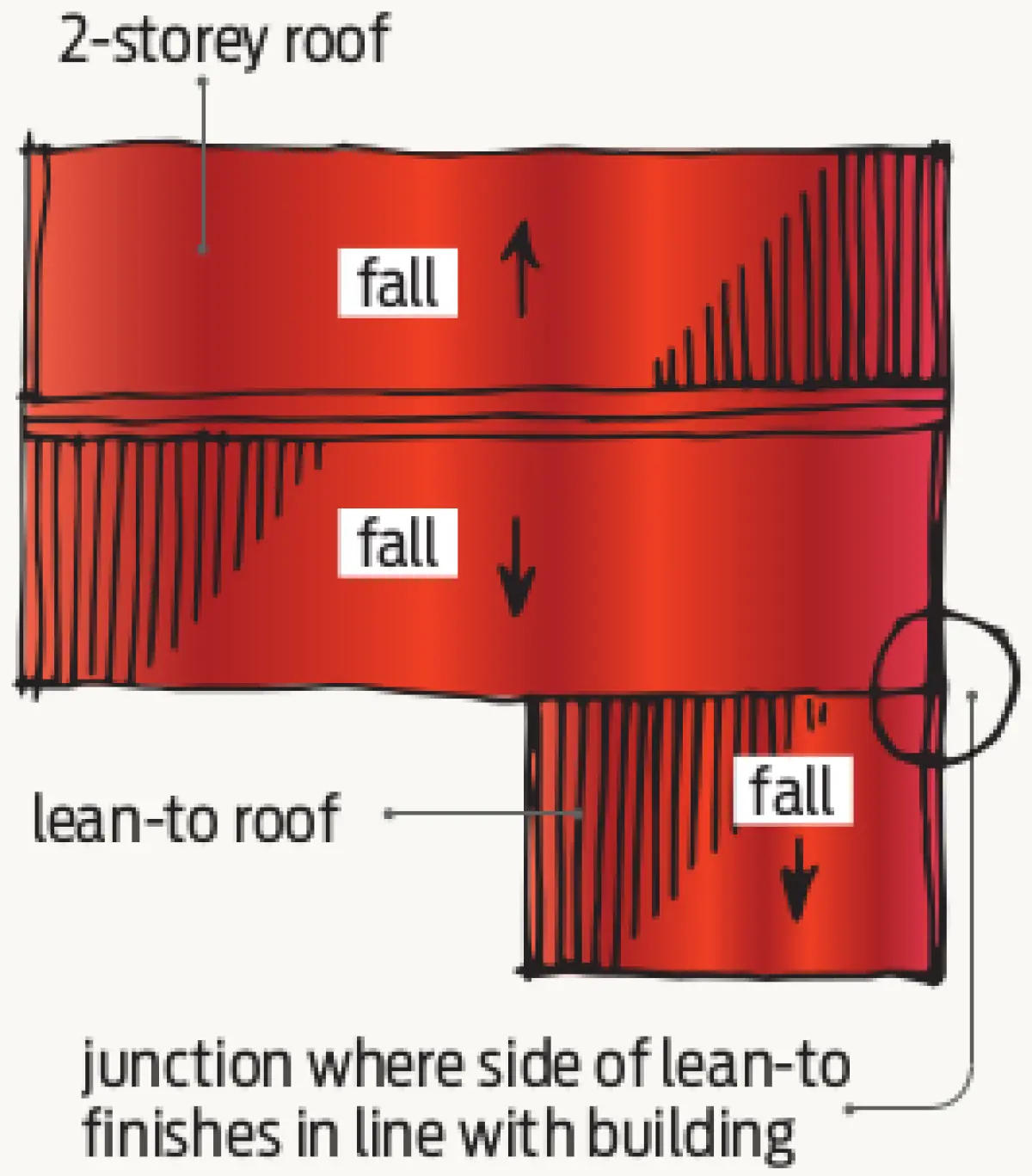
Acceptable Solution E2/AS1 doesn’t include details for roof-to-wall junctions where the side of a lean-to finishes in line with the main building and the roof slopes away from the upper wall (Figure 1).
Sequencing for installation
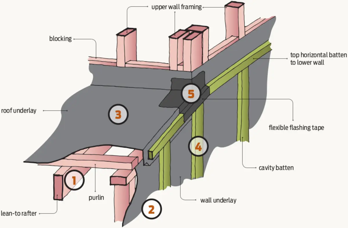
Figures 2–5 illustrate the steps for the construction of the detail where a sheet cladding is installed over a drained and vented cavity.
Step 1 – Complete all wall and roof framing.
Step 2 – Install wall underlay to lower-level walls.
Step 3 – Lay roof underlay to lean-to roof turned up higher wall and down face of wall.
Step 4 – Fit cavity battens to continuous side wall. Set horizontal batten to suit location of horizontal timber trim and flashing.
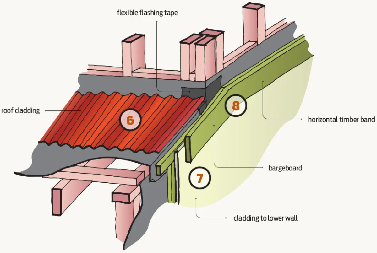
Step 5 – Fit flexible flashing tape to the corner at top of lean-to and dress over cavity battens.
Step 6 – Install roofing to lean-to.
Step 7 – Install cladding to lower level.
Step 8 – Fix bargeboard to side of lean-to and the horizontal timber trim.
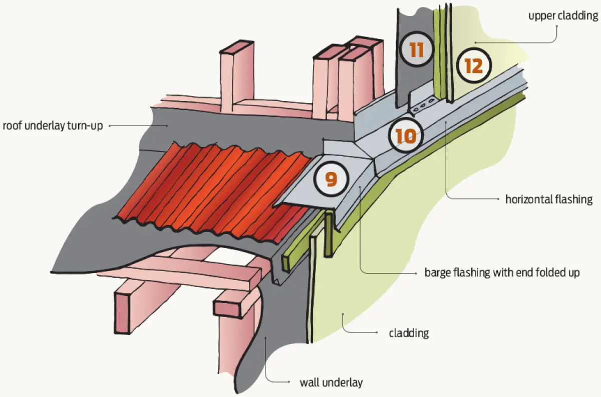
Step 9 – Barge flashing installed.
Step 10 – Fit horizontal flashing to cladding break
Step 11 – Install wall underlay to upper side wall. Lap over flashing upstand.
Step 12 – Begin cavity closure, battens and cladding to side wall but don’t complete to corner. Complete horizontal z flashing to side wall.
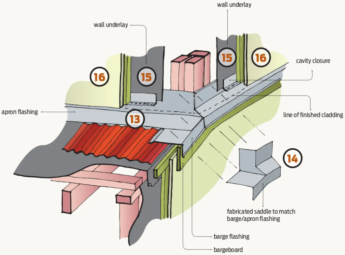
Step 13 – Install horizontal apron flashing.
Step 14 – Install fabricated corner flashing over apron, barge and horizontal break flashing.
Step 15 – Install wall underlay to upper return wall, lap over apron flashing upturn.
Step 16 – Complete cavity closures, cavity battens and cladding installation on upper wall.
Some specifics from E2/AS1
Specific requirements of Acceptable Solution E2/AS1 include that there must be:
- a 75 mm minimum wall cladding cover over the upstand
- a gap between the wall cladding and the roofing as per E2/AS1 Table 4.5.1.1
- cover over the roofing as per E2/AS1 Table 4.5.1.1 depending on wind zone and roof pitch.
Option to make this detail easier
Figure 6 provides a step at the lower wall junction so that the barge simply butts to the wall at right angles.