

Rainwater flows faster on steeper pitches, so the design of timber-framed chimney flashings is influenced by:
- the roof pitch
- the roof cladding – capacity of the troughs/pans, height of the profile and how the module of the cladding matches the dimensions of the chimney
- the size and shape of the chimney
- where the chimney is situated on the roof.
Another consideration is the risk of corrosion:
- from direct contact with another metal or substance
- as the result of run-off
- from poor design or installation allowing moisture to pond on the flashings.
Range of flashing types
Several types of flashing are typically used for chimneys:
- Soaker or underflashings that drain beneath the roof pan.
- Watershed, also known as overflashings or backflashings, that drain at the plane of the rib of the roof and are run up to the ridge. These are suitable when the chimney falls between the ridge purlin and the next purlin down the roof.
- Tray soaker flashings that drain at the plane of the roof pan into a gutter. These are useful when the chimney is located between the gutter purlin and the next purlin up the roof.
- Tapered flashings that drain from beneath the roof pan at the top and over the ribs at the bottom. These are also known as under/over or transition flashings.
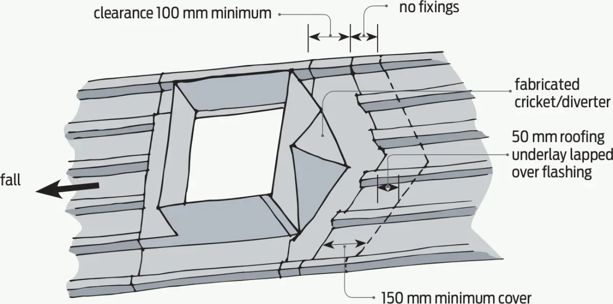
- Cricket flashing or diverter to channel water around the chimney.
Sealing and underlay
Flashings on unpainted and painted zinc and aluminium-zinc coatings are usually sealed with a neutral-cure silicone sealant in conjunction with mechanical fasteners. The sealant should be applied between the two sheets before they are fixed together.
Roof underlay should be lapped over the flashing so any condensation forming beneath the roof cladding above can drain.
Limited Acceptable Solutions
Acceptable Solutions covered by E2/AS1 are limited. There is a relationship between the width of the chimney, the catchment area above it and the type of roofing material. As the width of the chimney increases, the permissible length of roofing above the penetration decreases (see E2/AS1 Table 17 for profiled metal roofing and Table 9 for other roof claddings).
For all types of roofing, penetrations over 200 mm wide must be supported with additional framing. An alternative method of providing support is 12 mm H3 treated plywood. The plywood should be securely fastened to the structure and be separated from the flashing by roofing underlay.
Masonry and pressed metal tiles
For masonry tiles and pressed metal tiles, the minimum roof pitch is determined by the tile profile and material, the rafter length and, for masonry tiles, whether or not a roofing underlay is used. Refer to E2/AS1 Table 10.
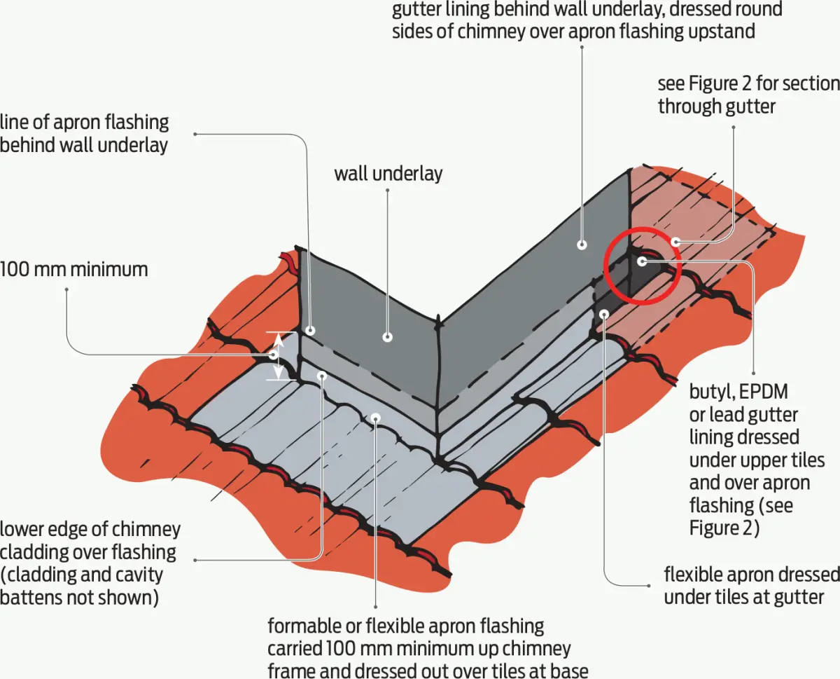
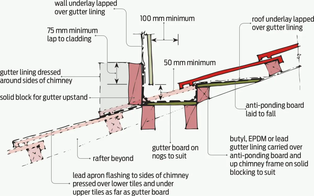
At the sides, including downslope, a lead apron flashing is used, returning 100 mm minimum up the chimney and dressed out over the tiles at the base and sides.
At the rear of the chimney, a butyl, EPDM or lead gutter lining is carried over an anti-ponding board. This forms a secret gutter behind the chimney, extending at least 125 mm up the chimney framing. It is then dressed down over the lower flashing (see Figures 1 and 2). The gutter must be at least 100 mm wide, although wider is recommended, to facilitate drainage and removal of debris.
Profiled metal roofing
E2/AS1 applies to penetrations up to 1,200 mm wide and roof pitches above 10°. It uses a soaker flashing based on details in E2/AS1 Figure 55 with a minimum 110 mm upstand to the chimney.
The flashing is lapped a minimum of 250 mm beneath the roofing sheets above. Cover dimensions above and below the chimney are given by dimension X from E2/AS 1 Table 7. The upslope face of the flashing upstand is splayed to shed water.
Membrane roofs
E2/AS1 permits a maximum penetration size of 1,200 × 1,200 mm for membrane roofs with the membrane extending up a coved upstand at least 150 mm high.
Alternative methods
Penetrations may be formed in roofs with any pitch down to 10° for corrugate and 3° for other profiles but will require specific design as alternative methods. Note that no penetrations are permitted in the portion of curved or draped roofs where the pitch falls below these limits.
The Acceptable Solution given in E2/AS1 shows the side gutter one full pan width on each side. For specific design, the capacity of the side gutters should be calculated based on catchment area, design rainfall and profile of the roofing material. For example, the capacity of a single corrugate valley is less than a single pan of a trapezoidal or trough profile roof cladding.
A metal flashing upslope of a chimney must be designed to prevent moisture or debris collecting behind the chimney, or the manufacturer’s warranty may be void due to the risk of deterioration and premature corrosion.
The NZ Metal Roof and Wall Cladding Code of Practice recommends using a cricket flashing (see Figure 3) where the width of the penetration is more than 600 mm or the roof pitch is below 10°.
The intention of a cricket flashing is to divert the water and debris around the chimney rather than allowing it to collect behind the chimney. This type of flashing must be submitted as an alternative method.
For more, See the NZ Metal Roof and Wall Cladding Code of Practice, available from www.metalroofing.org.nz/design.