


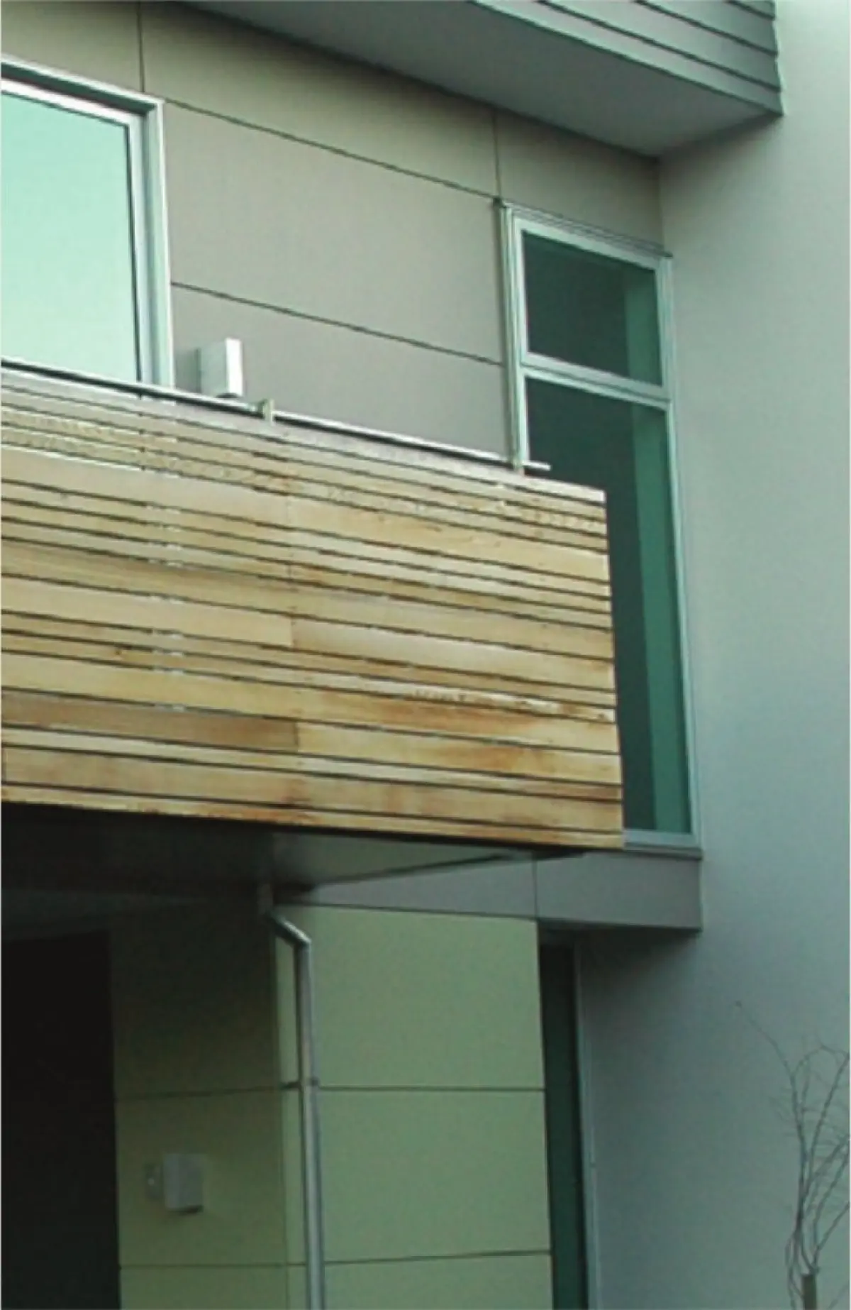
Waterproof decks with a membrane surface over an interior or exterior space have a high risk of weathertightness failure. This risk increases when solid balustrades fully enclose the deck area so that it contains any water. Failure often results in water entering the building assemblies and interior.
The design of waterproof decks involves the consideration of:
- selection of the membrane and its substrate
- substrate installation quality
- membrane transitions
- upstands and joints
- junctions with claddings
- drainage system
- provision of a trafficable surface.
This article discusses the drainage system design, which needs to effectively collect often substantial amounts of rainwater and drain it into a stormwater disposal system.
E2/AS1 for decks up to 40 m2
The size of the catchment area of the deck is important for drainage design. Generally, waterproof decks should be kept to a maximum size of 40 m2 – the maximum allowed when E2/AS1 is used as a means of Building Code compliance.
Where designing decks larger than 40 m2, consider increasing the fall of the deck surface to ensure sufficient runoff and increasing the number of outlets, overflows and size of gutters to suit the calculated discharge.
The focus of this article is the design of drainage for decks up to 40 m2 in size.
3° fall recommended
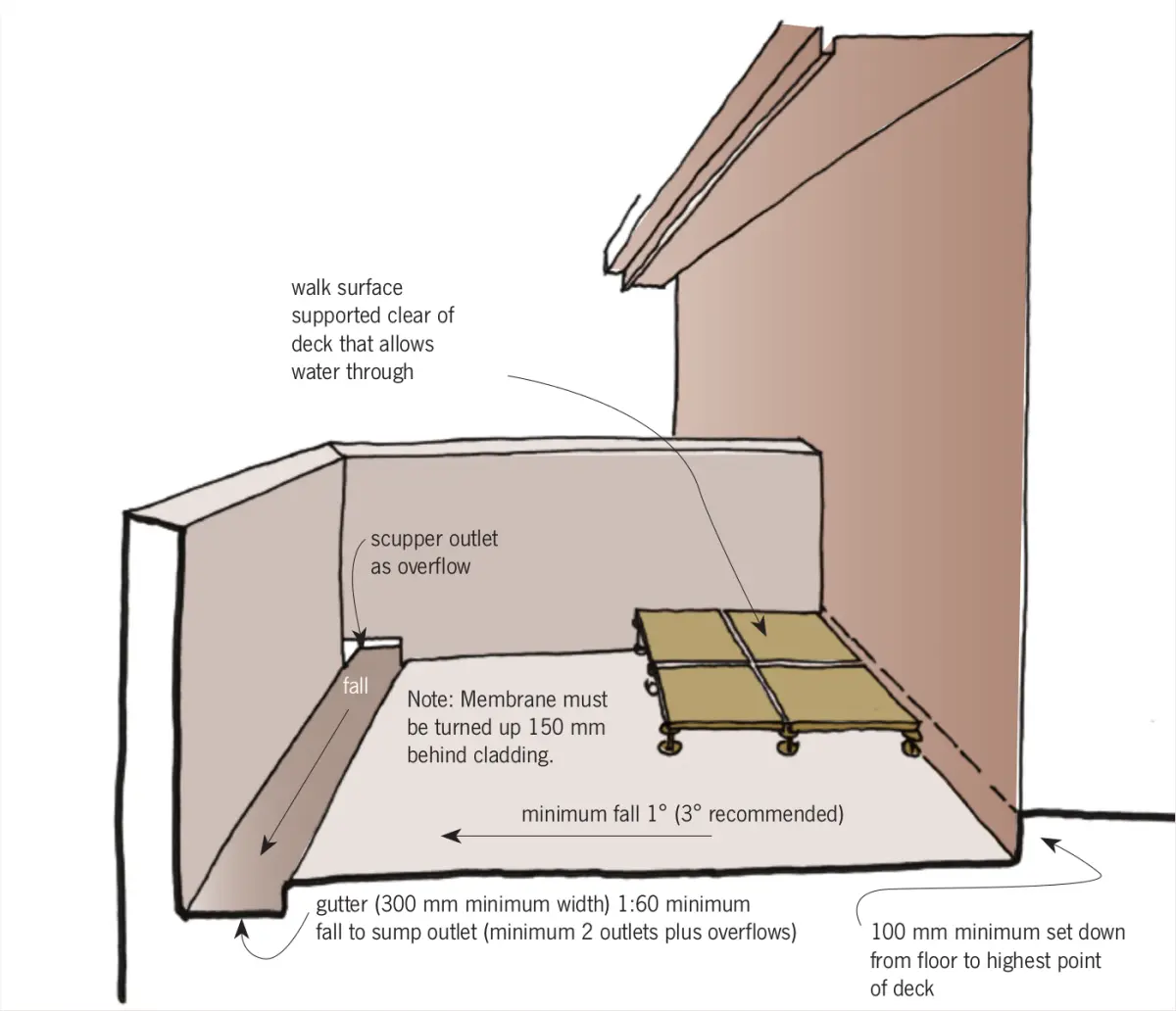
A key factor in deck design is having sufficient fall across the deck’s waterproof surface for surface water to be quickly removed (see Figure 1).
E2/AS1 requires a minimum fall of 1:60 (1°) across the waterproof surface. However, building to achieve a 1° fall is difficult, so BRANZ recommends a minimum fall of 3°. With 3°, any inconsistency in construction or sag in the structure should not compromise the drainage.
An increase in fall may be noticeable when walking on the deck, but this can be overcome by installing a removable deck raft as a level trafficable surface above the deck membrane.
No deflection or sagging in structure
With all membrane decks, it is important that the substrate is well supported to ensure a consistent fall across the deck surface and no deflection or sagging between supports that may cause ponding or slow drainage and drying.
Reducing the spans of the framing by 25% for a given joist size is one way of minimising the deflection or sagging risk.
Open-sided waterproof decks
Waterproof decks with open balustrades pose less of a drainage problem than fully enclosed decks. The deck membrane should be supported by a substrate set to fall towards the external edge of the deck. Ensure a minimum set down of 100 mm from the interior floor level of the building to the highest point on the deck membrane surface.
At the external edges, the waterproof membrane needs to be turned down and terminated to form a drip edge 50 mm beyond the face of any cladding. An external gutter is then installed along the entire length of the lowest side of the deck (the side that the water is falling towards), to collect water that will drain off the edge. The gutter needs sufficient capacity for the deck area and with fall to a drainage downpipe connected to the stormwater disposal system.
The deck is typically open on two or three sides so excess water can discharge over the sides of the deck or overflow from the external gutter during extreme weather conditions.
Enclosed waterproof decks
Waterproof decks fully enclosed with a solid balustrade rely on internal gutter systems to collect and discharge rainwater, sometimes under extreme conditions.
Rainfall intensities
It is recommended that design rainfall intensity is doubled for the locality of the building (used in the calculation of the drainage load) when the deck surface is fully enclosed, for example, for designing internal gutters. See E1/AS1 for design rainfall intensities.
Gutter location and size
Construct the deck membrane to fall towards the internal gutter. The gutter must be located to collect water from the entire deck surface, and the fall in the deck needs to be constructed so the entire surface drains towards the gutter.
The gutter may be located along one edge of the deck (see Figure 1) or in the centre, with the deck falling from two directions – away from the building and from the opposite direction at the same slope towards the central gutter. Falling from two directions reduces the level difference between the highest and lowest point on the deck surface.
The gutter, formed internally into the surface of the deck with the deck membrane, needs to be a minimum width of 300 mm and a minimum depth of 50 mm. The internal gutter can either drain into a vertical internal outlet pipe or horizontally via a scupper through the solid balustrade into an external rainwater head. In either case, the gutter needs to have a minimum fall of 1:60 (from E2/AS1) towards the outlet point.
Outlet pipe details
A minimum of two outlets (each with an overflow) is considered good design practice for enclosed decks – if one blocks, the other should still operate. This may seem excessive, but it provides drainage capacity to deal with even extreme weather events.
Where the gutter discharges into an outlet pipe, the pipe needs to be dressed into the sole of the gutter ensuring a waterproof junction between the pipe and the gutter membrane. The pipe should be a minimum diameter of 75 mm (suitable capacity for a 100 m2 deck with a rainfall intensity of 200 mm per hour) – more than adequate drainage for a 40 m2 deck. The opening of the pipe should be protected to prevent blockage and be connected to a stormwater disposal system.
If the pipe is to be concealed within a wall of the building, it must be fully sealed and pressure tested before enclosure.
Where an outlet pipe is used, allow for additional rainwater disposal with an overflow pipe sized the same as the outlet, capable of managing the full drainage capacity. An overflow can be installed as a scupper type outlet pipe, terminating 50 mm beyond the face of the balustrade cladding and with the maximum flood level at least 50 mm below floor level.
Scupper and rainwater head deck drainage
When the internal gutter discharges through a scupper formed through the solid balustrade, the scupper opening needs to be a minimum width of 200 mm and a minimum height of 75 mm. (A 300 mm wide × 100 mm high outlet is significantly easier to construct when formed on site in membrane and has a reduced risk of being blocked.) The scupper can be formed with a proprietary outlet and membrane or from membrane only. Watertight junctions are the key between the gutter and deck membrane and the scupper outlet, and the balustrade cladding where the scupper penetrates.
The scupper needs to incorporate a 50 mm discharge lip that forms a drip edge that ensures the efficient drainage of water off the edge into the rainwater head.
The rainwater head should be sized 100 mm wider than the scupper outlet width (50 mm each side) and be drained by a downpipe – both the downpipe and the rainwater head need to be of sufficient capacity for the calculated discharge. The opening of the downpipe should be protected to prevent blockage and be connected to a stormwater disposal system.
The rainwater head needs an overflow outlet positioned below the outlet level of the scupper, sized so excess water will drain from the overflow preventing the rainwater head filling beyond the scupper outlet level.
When using a scupper and rainwater head system for enclosed deck drainage, consider a scupper overflow pipe as extra protection. This is similar to having an outlet pipe for deck drainage.
Extra capacity equals extra protection
Good design practice for enclosed waterproof decks less than 40 m2 includes:
- providing more drainage outlets than required, with a minimum of two – this ensures that there is extra capacity for extreme weather events
- increasing the fall beyond the 1:60 requirement – while this may be enough to ensure deck drainage occurs, an increase in fall will enhance deck water runoff in extreme conditions.
There are other key aspects of waterproof deck design to consider for a watertight assembly, but following these basic deck drainage design principles will ensure water falling on the deck is efficiently collected and discharged.