Think of the word ‘wings’, and it is likely to conjure images of a prison compound or a bird flying free. Both images are equally relevant when it comes to establishing the definitions of blocks and wings under NZS 3604:2011 Timber-framed buildings. The two must work together under wind and earthquake load to ensure they don’t fly free of their own accord.
Calculating bracing demand
It is straightforward to work out the bracing requirements for each block and wing within a structure. However, the design must also consider the additional bracing requirements of shared walls.
The bracing in each shared wall must accommodate the demand of each individual block plus the demand of the wing with which it shares a wall.
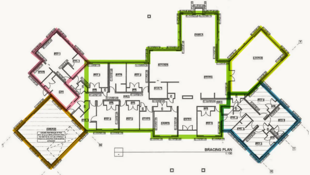
Let’s look at an example. Consider the structure shown in Figure 1 – a 500 m² single-storey house with a hip roof, which falls within the realm of NZS 3604:2011 for bracing. The design can be divided into five parts – a central block (marked green) and four wings (marked blue, yellow, pink and orange for the garage).
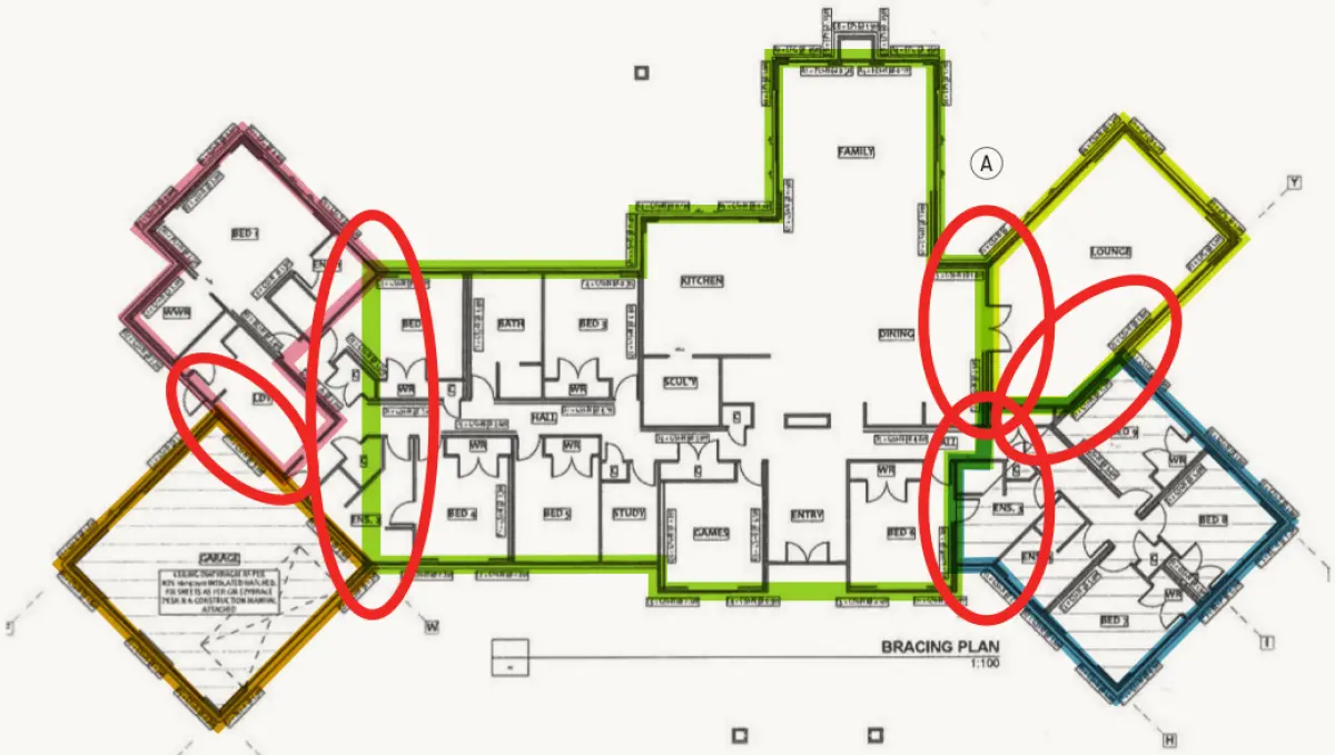
Shared walls require additional bracing
In this example, the bracing design requires additional capacity in the shared walls between the:
- green block and blue wing
- green block and yellow wing
- green block and pink wing
- green block and orange garage wing
- blue wing and yellow wing
- pink wing and orange wing.
These areas are indicated in Figure 2.
For instance, let’s say the bracing demand was calculated as 130 bracing units (BUs) for the green block and 100 BUs for the yellow wing in the shared wall. The bracing in the shared wall between the two (marked A) must therefore meet a minimum demand of 100 + 130 = 230 BUs.
Note that the garage (orange wing) may be large enough to require a structural diaphragm ceiling (>7.5 m wide). There are enough intersecting bracing lines adjacent to the family room to not require this ceiling to be a structural diaphragm.