


The same building is being used as in the previous article on subfloor bracing (see Build 132, pages 38–41) with additional information in Figures 1 and 2.
Data for calculation sheets for this example
Wind zone: Medium
Earthquake: Zone 2
Floor plan areas
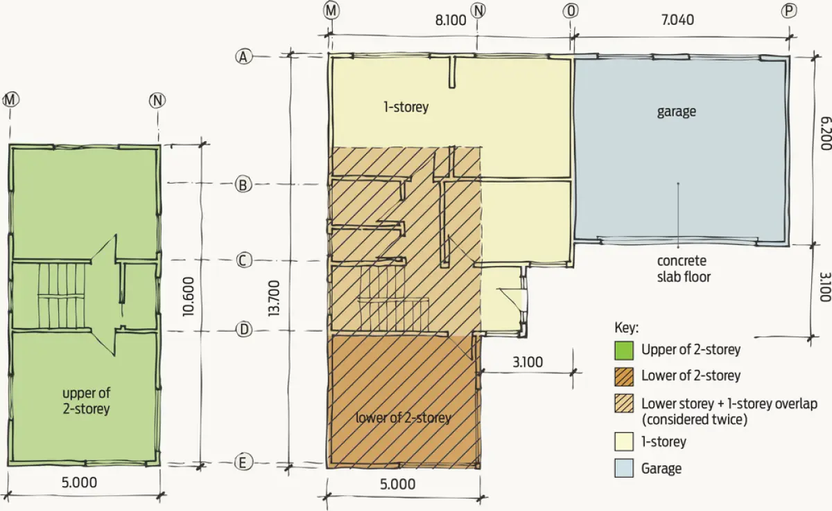
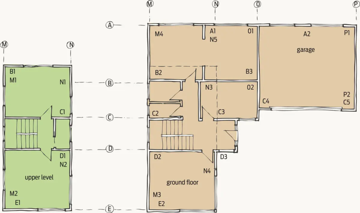
The example building is part 2-storey, part single-storey. The garage is on a slab, and the remainder has a subfloor. Because these have different wind and earthquake demands, the building is divided into four areas – upper of 2-storey, lower of 2-storey, single-storey and garage – and four calculations are needed, one for each of these.
The gross floor plan area for the:
- 2-storey = 10.6 × 5.0 = 53 m²
- 1-storey = 8.1 × 9.3 = 75.3 m² (for simplicity, the area has not been reduced for the porch entry)
- garage area = 6.2 × 7.040 = 43.6 m²
Soil type: Rock
Cladding weights: Light lower storey, upper storey and roof
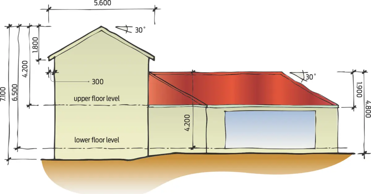
Roof pitch: 30 degrees, so choose 25–45 degrees
Heights for building:
- Lower of 2-storey to apex H = 6.5 m, h = 1.8 m
- Upper storey to apex H = 4.2 m, h = 1.8 m
- 1-storey to apex H = 4.8 m, h = 1.9 m
- Garage to apex H = 4.8 m, h = 1.9 m
Roof type and building dimension
As the roof pitch is over 25 degrees, when considering wind for the 2-storey part of the building, use the overall dimensions of the roof width and length.
- So, 2-storey section (upper and lower levels) are:
- length = 10.6 + 0.300 + 0.300 = 11.2 m
- width = 5.0 + 0.300 + 0.300 = 5.6 m
- single-storey: length = 6.2 + 3.1 = 9.3 m, width = 8.1 m (no roof overhangs)
- garage: length = 7.040 m, width = 6.2 m (no roof overhangs).
Bracing lines and spacings
Use the same bracing layout as for the subfloor in Build 132 (see Figures 2 and 7). The maximum allowed spacing of bracing lines for walls is 6 m (NZS 3604:2011 clause 5.4.6).
For simplicity, the bracing demand for the 1-storey area has not had the area of overlap with the 2-storeys deducted. Blue entries in Figure 5 indicate overlap of demand.
The garage bracing lines are greater than 6 m apart so the garage will require a diaphragm ceiling. Diaphragm ceiling requirements are covered in NZS 3604:2011 clause 13.5 and minimum BUs requirements are in clause 5.6.2.
Alternatively, it may be possible to use dragon ties, which allow bracing lines spacing to be extended to 7.5 m. For walls with dragon ties attached, see clauses 8.3.3.1 to 8.3.3.4.
Bracing lines less than 1 m apart and parallel are considered to be in the same bracing line.
Wall bracing maximum ratings for attachment to:
- timber framed floors = 120 BUs/m
- concrete floors = 150 BUs/m.
See Figure 7 for the layout of the various braced sections.
Bracing demand per line
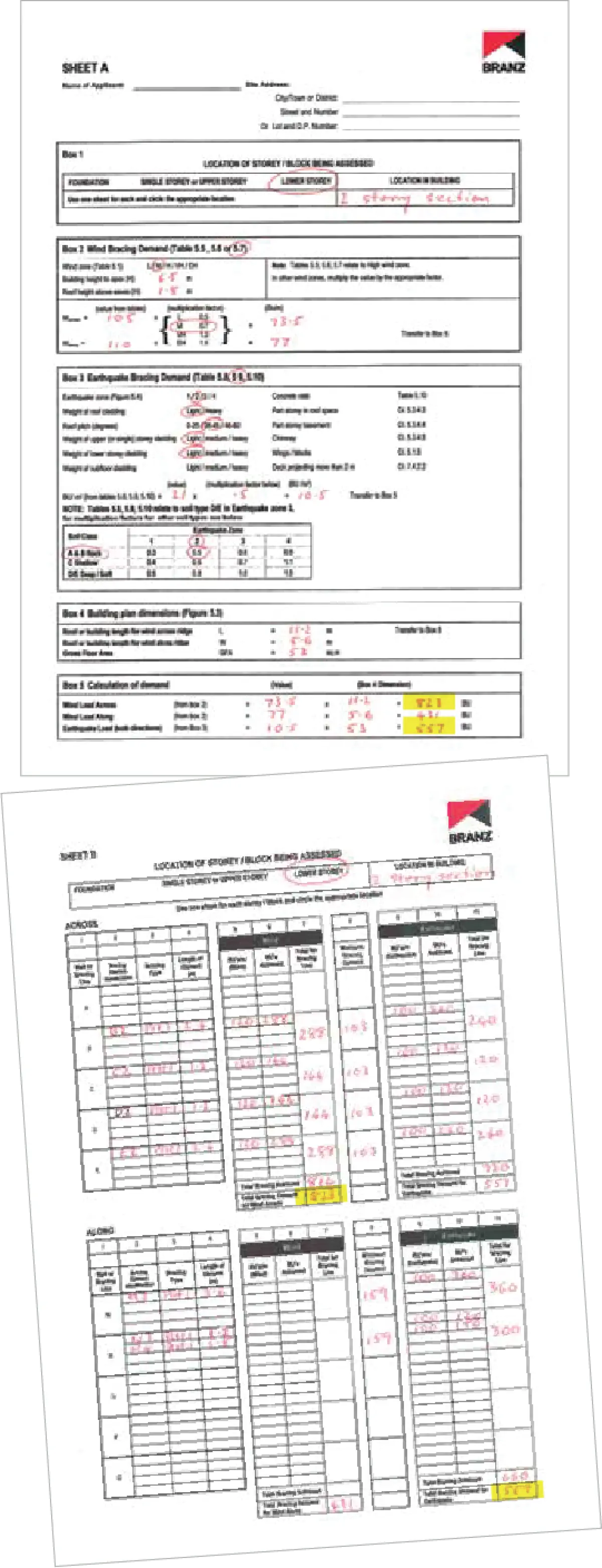
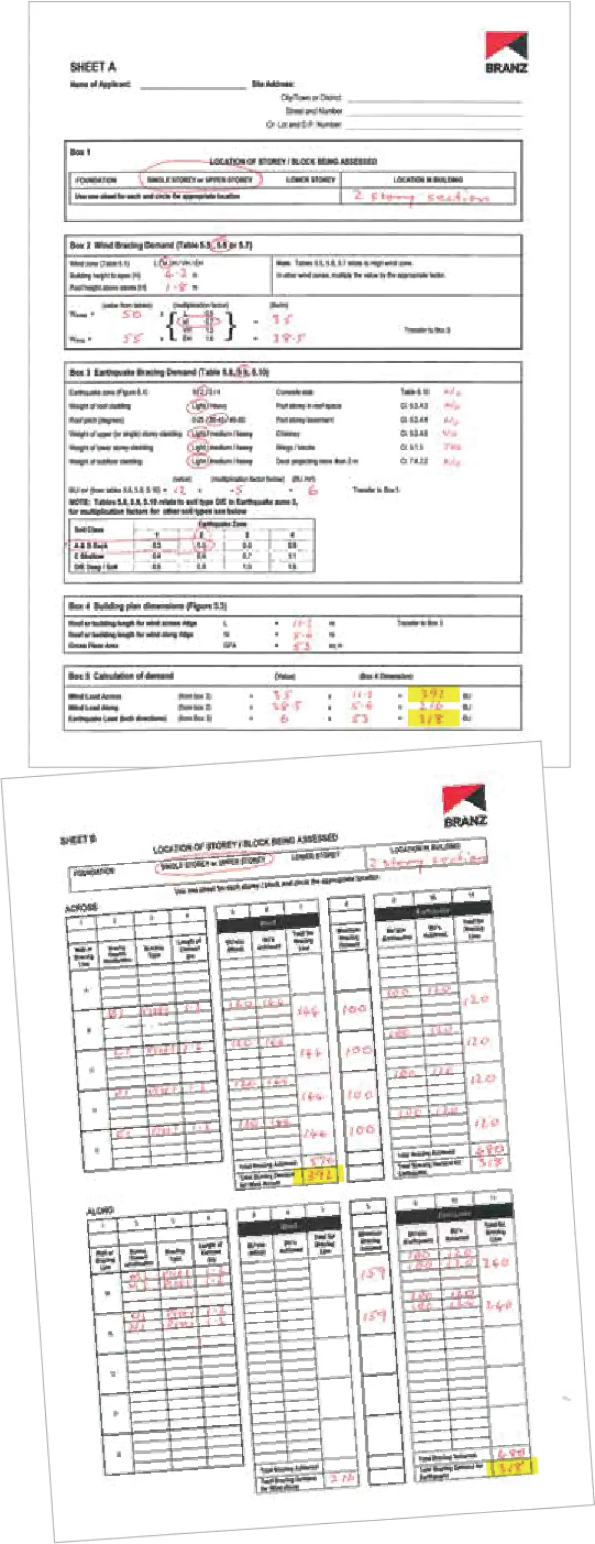
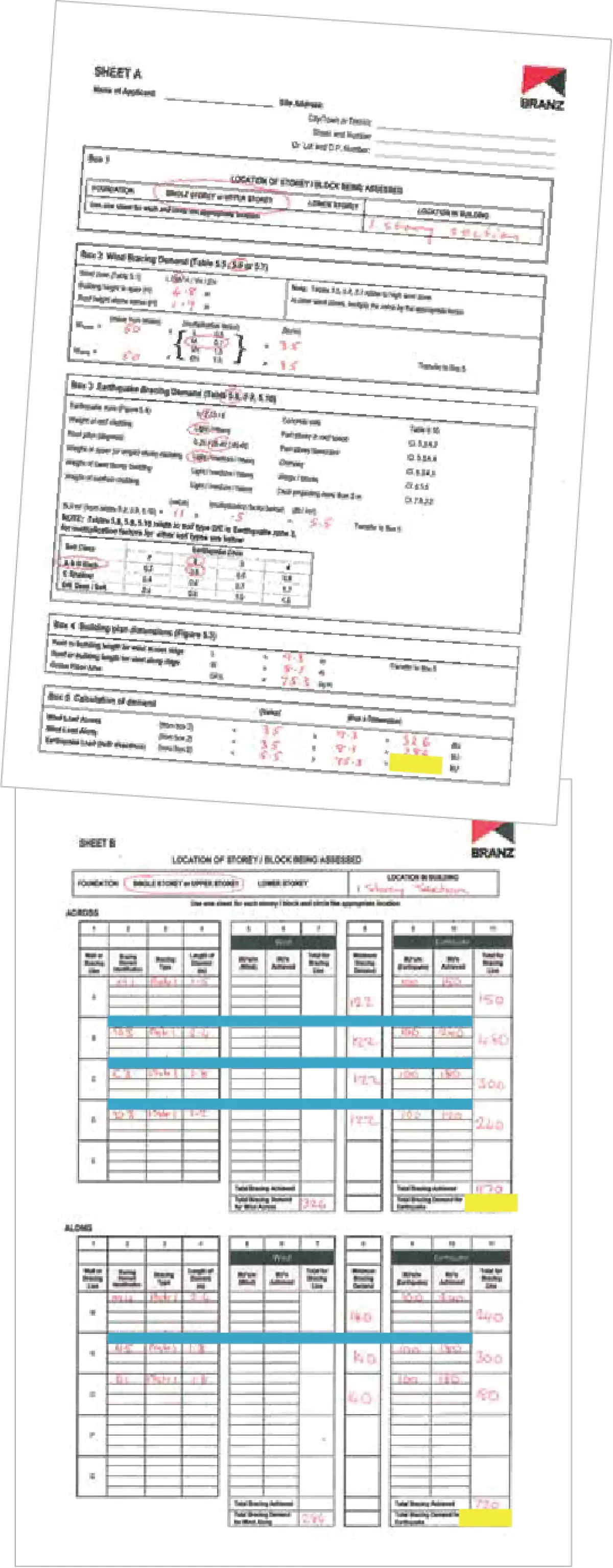
Complete the bracing calculation sheets (see Figures 3–6) to obtain bracing demand. Always use whichever has the higher demand for wind or earthquake – these have been highlighted in the calculation sheets as the minimum bracing demand required.
The minimum bracing demand per bracing line is the greater of:
- 15 BUs/m of bracing line or
- 100 BUs or
- 50% of the total demand, divided by the number of bracing lines in the direction being considered.
Minimum BUs per line in example
Lower level of the 2-storey (see Figure 3b):
- Lines B, C, D, E = 5 m × 15 = 75 BUs or 100 BUs or 824/2 divided by 4 lines = 103 BUs
- Lines M, N = 10.6 × 15 = 159 BUs or 100 BUs or 557/2 divided by 2 lines = 139.2 BUs
Upper level of 2-storey (see Figure 4b):
- Lines B, C, D, E = 5 m × 15 = 75 BUs or 100 BUs or 392/2 divided by 4 lines = 49 BUs
- Lines M, N = 10.6 × 15 = 159 BUs or 100 BUs or 318/2 divided by 2 lines = 79.5 BUs
Single level (see Figure 5b):
- Lines A, B, C, D = 8.1 × 15 = 121.5 BUs or 100 BUs or 414/2 divided by 4 lines = 51.8 BUs
- Lines M, N, O = 9.3 × 15 = 139.5 BUs or 100 BUs or 414/2 divided by 3 lines = 69 BUs
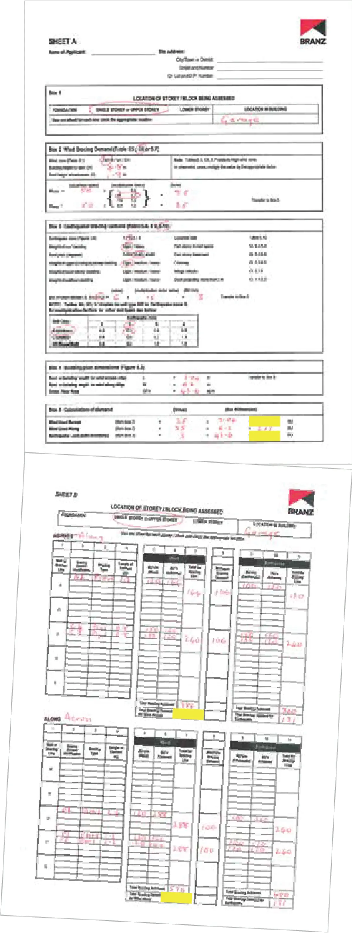
Garage (see Fig 6b):
- Lines A, C = 7.040 × 15 = 105.6 BUs or 100 BUs or 247/2 divided by 2 lines = 62 BUs
- Lines O, P = 6.2 × 15 = 93 BUs or 100 BUs or 217/2 divided by 2 lines = 54.25 BUs
Transfer these values to the appropriate bracing sheets.
Choose bracing element
Bracing materials used are sheet products (ply, plasterboard, fibre cement and so on), concrete, concrete blocks or metal components. All bracing units are achieved using proprietary products that have had their bracing rating validated by the P21 test. The rating may vary for earthquake, wind and also for the length used. For example, a sheet material that is rated as achieving 120 BUs for wind, may have a lesser rating when used for earthquake or the sheet width is less than the manufacturer’s minimum width.
BUs ratings are all derived from testing materials at 2.4 m high. Bracing materials installed at other heights will require the BUs achieved to be calculated for the height used using clause 8.3.1.4 of NZS 3604:2011.
In this example
For this exercise, a generic plasterboard has been used with a rating of 120 BUs for wind and 100 BUs for earthquake. This has been given the designation ‘Plstr 1’ in the worksheets.
For the bracing sheets either side of the garage door in bracing line C, a generic ply has been chosen, designated in the worksheet as ‘Ply 1’. This has a rating of 150 BU/m for wind and earthquake. Proprietary sheet linings tested by manufacturers usually require some form of hold-downs – always follow the manufacturer’s details. Never mix details from different systems.