



If building failure occurs in a severe storm, it is usually at the connections between the structural components of the roof (purlin to rafter or truss top chord), the connection of the rafter/truss to the top plate or the top plate to the studs. It is much less common for the roof cladding to detach from the purlins or battens – this generally occurs where the fixing or the roofing has become weakened, for example, by corrosion of the roof fixing or the roofing.
Once the roof or part of the roof has failed, the wind loading on other parts of the building is altered, which may cause further structural failure plus other damage, such as water entry.
Wind effect on pitched roofs
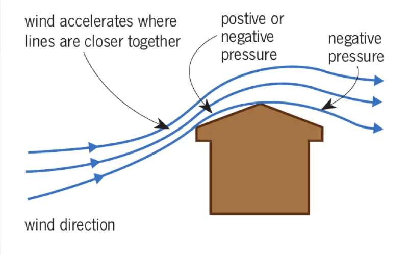
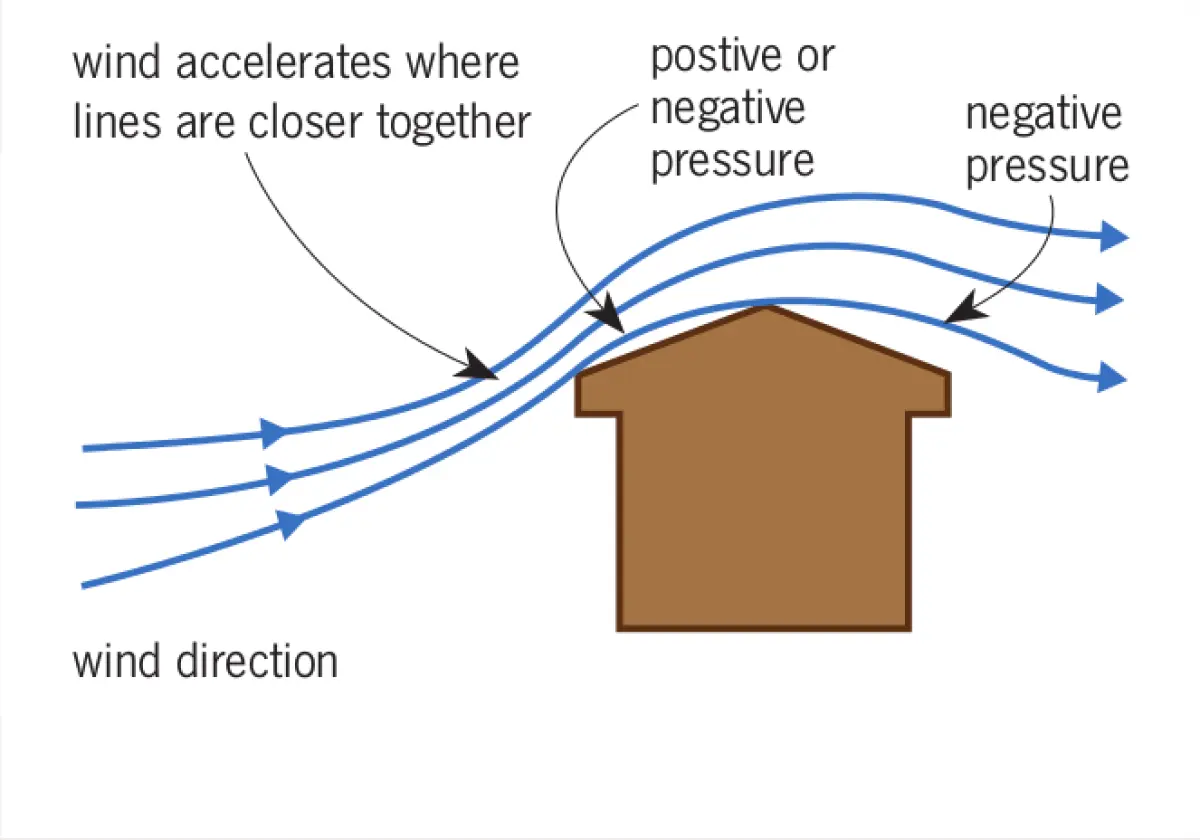
Media reports often describe roof failure as the roof being ‘blown’ off the building, but this is not what occurs. Wind flow changes speed as it passes over and around a building, particularly as it accelerates over a roof plane (see Figure 1). The wind flow over the roof causes localised pressure reductions that create an upward force on the roof surface – the same effect that enables the airflow across a wing to lift an aeroplane.
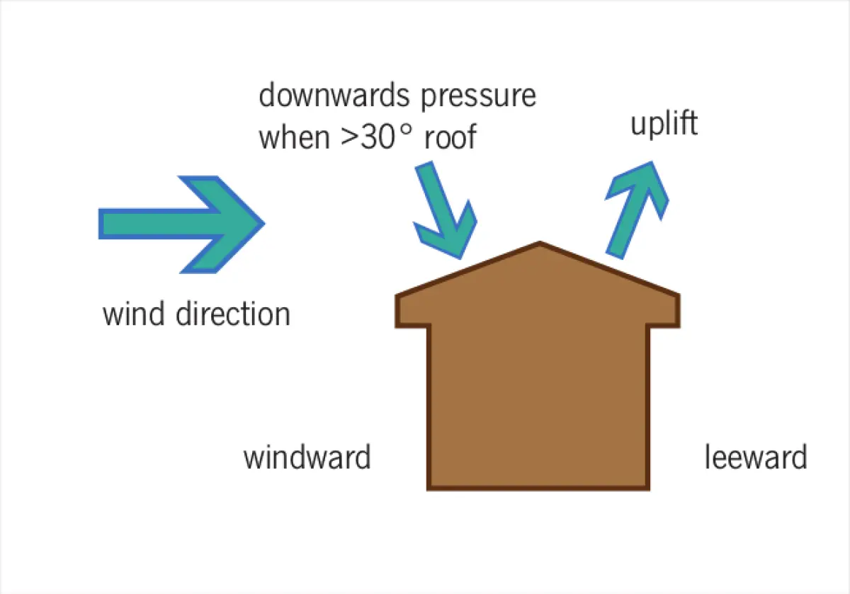
The roof pitch, wind speed and wind direction are the key determinants in how the wind will act on a roof structure. Roof pitch significantly impacts the pressures imposed (see Table 1 and Figures 2 and 3) as do sharp edges, corners and appendages (such as eaves and chimneys). By disrupting the wind flow and creating vortexes and eddies, combined with fluctuating wind speeds (wind seldom blows steadily), variable pressures occur.
The most vulnerable parts of the roof are at the edges, in particular, eaves and verges, and to a lesser extent, ridges.
Critical roof framing connections
Critical to roof performance under wind loads are the:
- fixing of the purlin or batten to the rafter/top chord
- the fixing of rafter or trusses to the top plate
- fixing of the top plate to the studs.
Details of the requirements for these connections are given in NZS 3604 and depend on the wind zone the building is constructed in. For specific design, the connections will have to be specifically engineered to accommodate the design wind speed.
Roof cladding failure less common
Lightweight roofing, such as profiled sheet metal, is more easily lifted by strong winds than other heavier roofing materials.

Where failure of the roof cladding occurs, it is generally because:
- the fixing of the roofing to the purlin or batten is inadequate
- the fixing or cladding has deteriorated
- the span for the roofing profile (and wind zone) has been exceeded.
| Roof pitch | Effect on windward slope | Effect of leeward slope |
|---|---|---|
| <17° | uplift from negative pressure | uplift from negative pressure |
| 17–30° | uplift or downwards | uplift from negative pressure |
| >30° | downwards from positive pressure | uplift from negative pressure |
For example, old corrugated steel roofing was typically fixed to purlins or sarking using lead-headed nails fixed through alternate crests near the ridge, eaves and verges, usually reduced to every third crest over the main part of the roof.
Weather, corrosion and people walking on the roof often caused the nails to become loose, reducing their effective holding strength. Sometimes the lead head, which provides the weather resistance, detaches from the nail, reducing its ability to resist uplift and allowing the ingress of moisture, causing the nail shaft to corrode and lose resistance to uplift forces.
Case study: the loss of a roof
During a severe storm, the low-pitched (approximately 6°) roof of a house lifted off and landed in a neighbour’s garden. The damaged roof was 0.6 mm long-run trough-section galvanised steel with timber still attached to it. It had been installed over the original flat roof.
THE PROBLEM
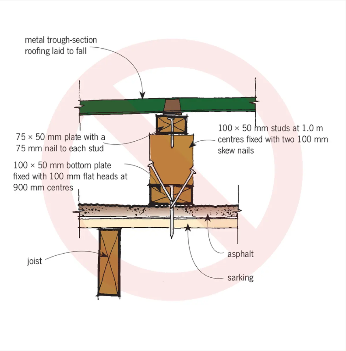
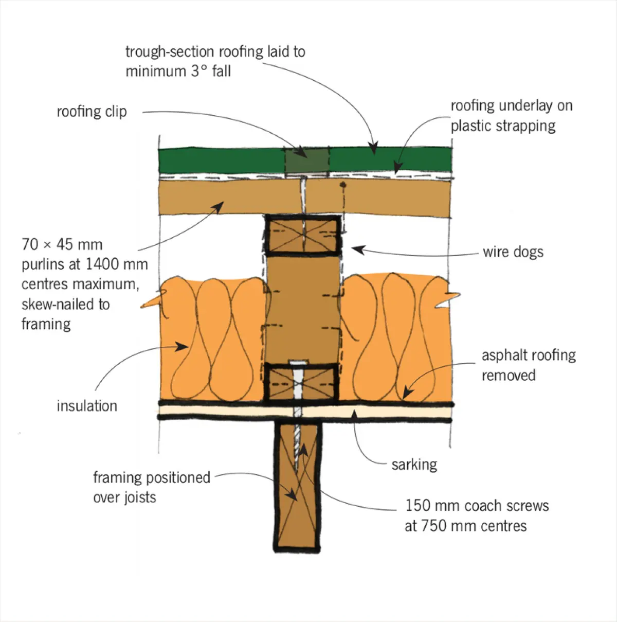
The original roof of the house was an asphalti-mpregnated membrane laid over sarking. When it began to leak, a new roof was installed over the existing roofing. Timber framing consisting of 100 × 50 mm bottom plates and studs and 75 × 50 mm top plates was installed over the flat asphalt roof to create a fall. The framing was fixed at 1.2 m centres and the sheet metal roofing was laid over this (see Figure 4).
As the top plates were still attached to the roofing, failure had occurred at the connection between the top plate and the studs.
THE SOLUTION
Since the roof had failed, a building consent was required. The design solution outlined here is not covered by NZS 3604 Timber framed buildings as it is a specifically engineered design for the site conditions.
To repair the roof, the wind zone was identified and both the framing and original membrane roof were removed. The sarking was inspected and found to be sound so new framing, similar in concept to the previous framing, was constructed using 90 × 45 mm H3.1 treated timber. The framing was installed at every second joist line (approximately 900 mm centres) and fixed through the sarking into the joists using 150 mm coach screws at 750 mm centres (see Figure 5). The studs were connected on both sides to the top and bottom plates with wire dogs, and 70 × 45 mm purlins were fixed with two 100 × 3.75 mm skewed nails and one wire dog at maximum 1400 mm spacings.
New zinc-aluminium alloy-coated, prepainted steel, trough-section roofing with matching flashings was installed using concealed fixing straps and laid over roofing underlay. As a bonus, the previously uninsulated roof space was insulated at the same time.
Inspect older roofs
Before 1978, there were no specific sizing or fastening requirements for purlins. With the introduction of NZS 3604, wind zones were identified and sizes, spacings and spans for purlins were defined. Subsequent amendments to NZS 3604 have upgraded the fixing requirements, particularly the fixing of purlins and the tying of the roof structure to the wall framing.
Roofs of older houses, particularly those built before 1978 in high wind zones with roof pitches of less than 17°, may have a higher risk of roof damage. They should be inspected to check the condition of roofing and fixings.
Details for retrofits
Table 2 (see page 16) provides a range of retrofit recommendations and solutions that can generally be installed from within the roof space with no or minimal disruption to the external cladding.
| Design wind area | Current wind zone | Purlin fixing (light roofs only) | Rafter fixing (light roofs only) | Truss fixing (light roofs only) |
|---|---|---|---|---|
| Pre-1978 houses | ||||
| None specified | Low | Do nothing. | Do nothing. | No trusses. |
| Medium | ||||
| High | If rafter is radiata pine or Douglas fir, add single Z nail to purlin/rafter connection in periphery areas. | |||
| Very high | Add L bracket between the rafter and plate, nail (4) and screw (2) in place. | |||
| 1978–90 houses | ||||
| Low | Low | Add single Z nail to purlin/rafter connection in periphery areas. | If contributing area to connection is 1.5–2.0 m², add L bracket between the rafter and plate, nail (4) and screw (2). | Do nothing. |
| Medium | If contributing area to connection is 1.0–2.0 m², add L bracket between the rafter and plate, nail (4) and screw (2). | |||
| High | If contributing area to connection is up to 2.0 m², add L bracket between the rafter and plate, nail (4) and screw (2). | For trusses spanning 7.6 m with fixings weaker than 2 skewed nails and 2 wire dogs, add L bracket between the rafter and plate, nail (8) and screw (2). | ||
| Very high | For trusses spanning 5.2 m with fixings weaker than 2 skewed nails and 2 wire dogs, add L bracket between the rafter and plate, nail (8) and screw (2). | |||
| Medium | Low | Do nothing. | Do nothing. | |
| Medium | If contributing area to connection is 1.0–2.3 m² and there are no wire dogs, add L bracket between the rafter and plate, nail (4) and screw (2). | |||
| High | If contributing area to connection is 0.7–2.3 m² and there are no wire dogs, add L bracket between the rafter and plate, nail (4) and screw (2). | For trusses spanning 7.6 m with fixings weaker than 2 skewed nails and 2 wire dogs, add L bracket between the rafter and plate, nail (8) and screw (2). | ||
| Very high | If contributing area to connection is 0.5–3.2 m² and there are no wire dogs, add L bracket between the rafter and plate, nail (4) and screw (2). | For trusses spanning 5.2 m with fixings weaker than 2 skewed nails and 2 wire dogs, add L bracket between the rafter and plate, nail (8) and screw (2). | ||
| If contributing area is greater than 3.2 m² and nails and wire dogs are in place, add L bracket between the rafter and plate, nail (4) and screw (2). | ||||
| High | Low | Do nothing. | Do nothing. | |
| Medium | If contributing area to connection is 2.7–3.7 m² and there are no wire dogs, add L bracket between the rafter and plate, nail (4) and screw (2). | |||
| High | If contributing area to connection is 1.8–3.7 m² and there are no wire dogs, add L bracket between the rafter and plate, nail (4) and screw (2). | For trusses spanning 7.6 m with fixings weaker than 2 skewed nails and 2 wire dogs, add L bracket between the rafter and plate, nail (8) and screw (2). | ||
| Very high | If contributing area to connection is 1.3–3.25 m², add L bracket between the rafter and plate, nail (8) and screw (4). | For trusses spanning 5.2 m with fixings weaker than 2 skewed nails and 2 wire dogs, add L bracket between the rafter and plate, nail (8) and screw (2). | ||
| If contributing area greater than 3.25 m² and wire dogs in place, add L bracket between the rafter and plate, nail (4) and screw (2). If no wire dogs, nail (8) and screw (4). | ||||
| 1990–99 houses | ||||
| Not applicable | Low | If contributing area is greater than 0.81 m², add single Z nail to purlin/rafter connection in periphery areas. | If contributing area to connection is 1.5–2.0 m², add L bracket between the rafter and plate, nail (4) and screw (2) in place. | Do nothing. |
| Medium | If contributing area is greater than 0.54 m², add single Z nail to purlin/rafter connection in periphery areas. | If contributing area to connection is 1.0–2.3 m² and there are no wire dogs, add L bracket between the rafter and plate, nail (4) and screw (2). | ||
| High | If contributing area to connection is 1.8–3.7 m² and there are no wire dogs, add L bracket between the rafter and plate, nail (4) and screw (2). | For trusses spanning 7.6 m with fixings weaker than 2 skewed nails and 2 wire dogs, add L bracket between the rafter and plate, nail (8) and screw (2). | ||
| Very high | If contributing area to connection is 0.5–3.7 m² and there is no cyclone tie, add L bracket between the rafter and plate, nail (4) and screw (2). | For trusses spanning 5.2 m with fixings weaker than 2 skewed nails and 2 wire dogs, add L bracket between the rafter and plate, nail (8) and screw (2). | ||
| 1999 and later houses | ||||
| Do nothing for all options. |
Note: Nail refers to 30 × 3.15 mm galvanised nails. Screw refers to Type 17 14 g × 50 mm hex head galvanised screws. L brackets must be no less than 4.7 kN.
For more: Download the full free BRANZ study report SR 187 (2008) Retrofitting of houses to resist extreme wind events from www.branz.co.nz.