NZS 3604:2011 Timber-Framed Buildings sets out the requirements for bracing lines. Bracing lines are imaginary lines running along or across the full length or width of a timber-framed building. They have no physical significance but are required to control the positioning of bracing elements.
Maximum and minimum spacing
The maximum spacing of bracing lines is:
• 6 m apart in both directions for bracing elements at ground floor and above
• 5 m apart in both directions for subfloor.
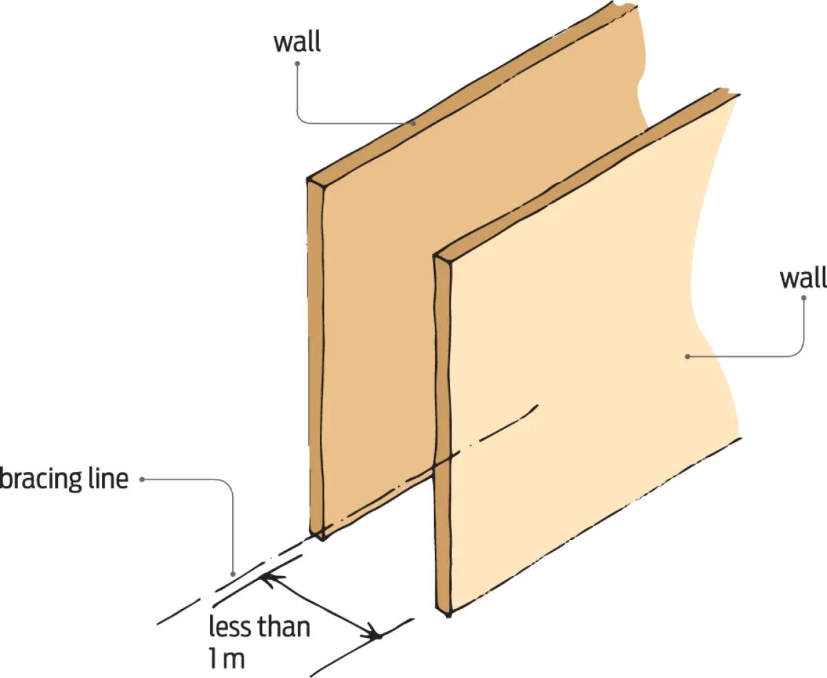
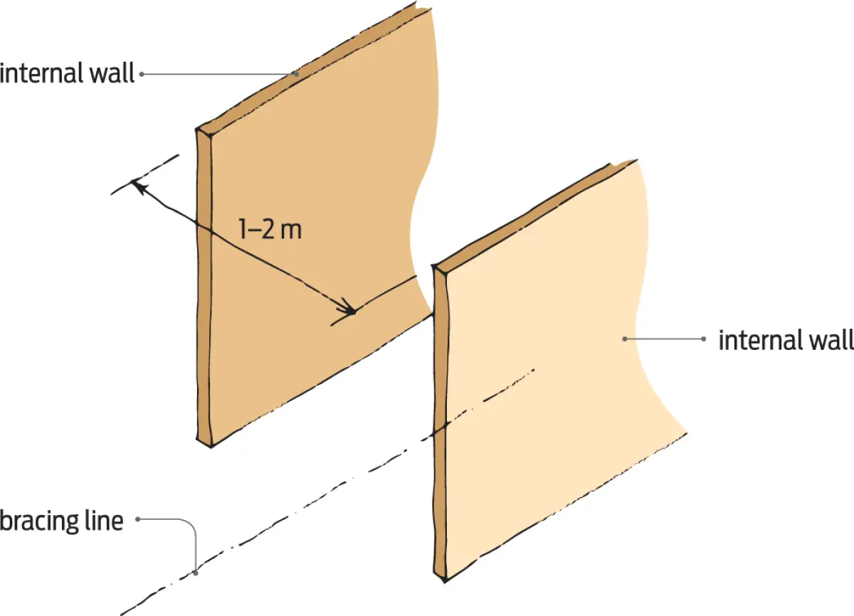
Parallel bracing lines that are:
• less than 1 m apart are considered to be a single line (see Figure 1)
• between 1 and 2 m apart can be considered as single or separate lines (see Figure 2)
• over 2 m apart are considered as separate lines.
This helps to evenly distribute the bracing and avoid concentrating bracing in one area.
No bracing lines in diaphragms
Diaphragms that comply with NZS 3604:2011 clause 5.6.1 require bracing lines on all four sides of the perimeter but no bracing lines within the diaphragm. The maximum size of diaphragms in clause 5.6.1 are 12 m long with an aspect ratio no greater than 2. The aspect ratio is length divided by width, for example, a diaphragm measuring 12 × 6 m or 8 × 4 m has an aspect ratio of 2.
Floor diaphragms should comply with clause 7.3 and ceiling diaphragms with clause 13.5.
External bracing lines
The minimum capacity of external bracing lines is the greater of:
• 100 bracing units (BUs)
• 15 BU/m of external wall length on the bracing line
• 50% of the total demand divided by the number of bracing lines in the direction being considered (along or across).
Dragon ties
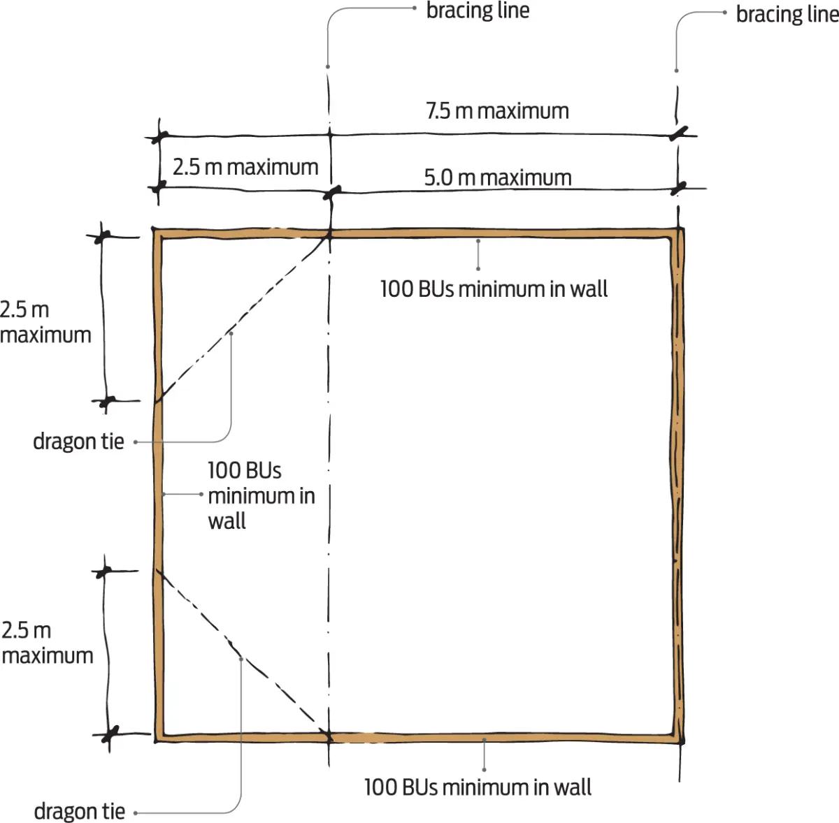
Dragon ties may be used with a braced wall system to permit a maximum room size of 7.5 × 7.5 m. The dragon tie fixing must be no more than 5 m from the next inside bracing line (see Figure 3).
Walls with dragon ties attached to the top plate must have bracing capacity of at least 100 BUs.
Dragon ties can only be attached in pairs across corners. They must be no more than 2.5 m from the corner and be a continuous piece of at least 90 × 35 mm. For fixings, see NZS 3604:2011 clause 8.3.3.4.
For more on dragon tie requirements, see clause 8.3.3.
Parallel external walls
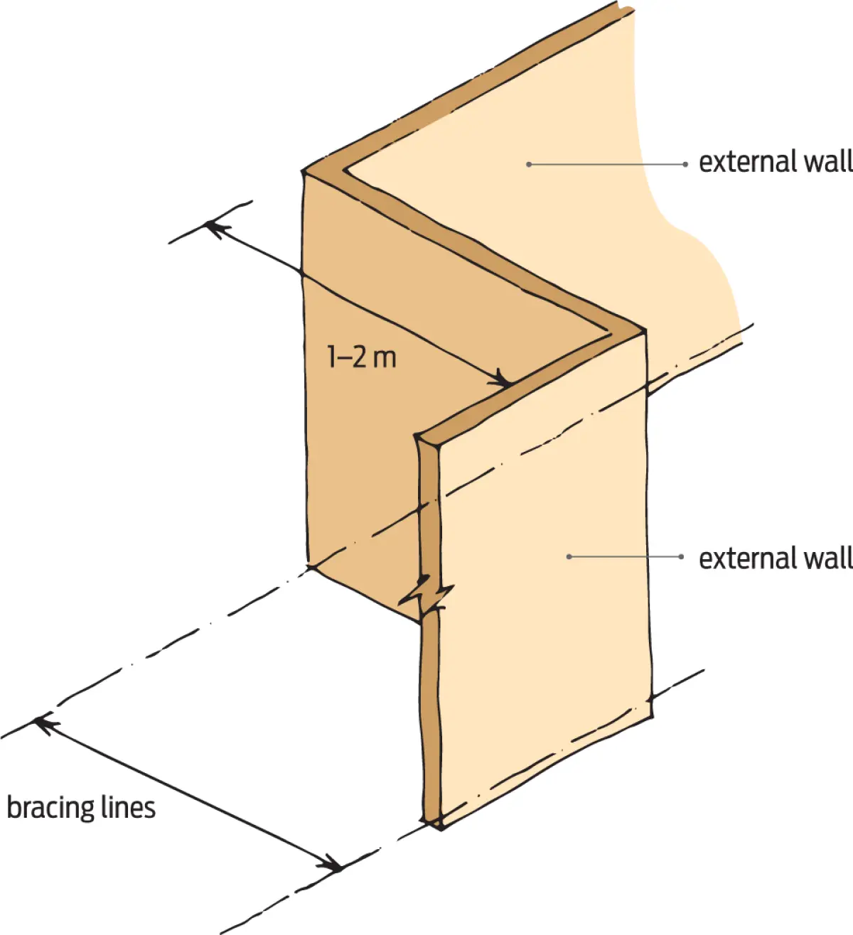
Parallel external walls offset between 1 and 2 m from each other may be treated as either one bracing line or as two separate lines (see Figure 4).
Internal bracing lines
The minimum capacity of internal bracing lines is the greater of:
• 100 BUs
• 50% of the total demand divided by the number of bracing lines in the direction being considered (along or across).
Each internal bracing line can have bracing from either or both:
• wall bracing elements in the internal wall on the bracing line
• pairs of wall bracing elements in internal walls up to 2 m apart, one each side of the bracing line and parallel to it.