

Bounce in a floor may become noticeable when deflections exceed around 1/300 of the joist span (that is, 1 mm deflection for every 300 mm of span) or 1/360 where floors are tiled.
A timber floor that bounces generally indicates floor joists that are inadequately sized for their span. These may have been undersized at the design stage, but sometimes their depth has been compromised during construction or renovation work when some of the timber has been removed, for example, to install a pipe or waste.
Holes and notches in floor joists
Under NZS 3604:1999 Timber framed buildings, residential floors must be designed to support a 1.5 kPa (150 kg/m2) load, which is approximately equivalent to two average adults standing on 1 square metre of floor. NZS 3604:1999 Table 7.1 gives maximum spans and spacings for timber joists of specific sizes and grades. Any reduction in the depth of joists, such as holes or notches, or any increase in the spacing of the joists will compromise their design strength performance.
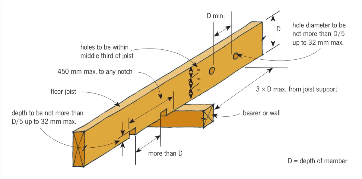
Clause 7.1.7 and Figure 7.8 of NZS 3604:1999 put limitations on the size, location and number of holes and notches that may be cut into floor joists (see Figure 1).
An exception to the limitation of paragraph 7.1.7 is permitted when notches do not reduce the effective depth of the joists. Paragraph 7.1.7.4 states that no holes or notches are permitted in cantilevered joists, except as permitted in paragraph 7.1.5.2, which requires that the joist depth at any notch, step or hole occurring within two-thirds of the cantilever support must be at least the depth required by Table 7.2.
Case study of a bouncy floor
An upstairs bedroom floor was found to deflect 8 mm over a span of 3.4 m, giving a deflection of 1⁄425. While less than the recommended maximum, it was sufficiently noticeable and annoying for the owners of a newly purchased home to investigate why it was occurring.
THE PROBLEM
Removal of part of the floor revealed MSG 8 grade, 190 × 45 mm timber joists with a 3.4 m span spaced at a maximum of 450 mm centres – just within the limits of NZS 3604:1999 (the maximum permitted according to Table 7.1 is 3.45 m).
However, further investigation of the floor structure revealed that every floor joist had a hole drilled through it at approximately midspan to accommodate the wastewater pipe that ran through the floor space perpendicular to the joists from the adjacent ensuite bathroom. The holes reduced the effective depth of the joists to less than that permitted for their span under NZS 3604:1999.
THE SOLUTION
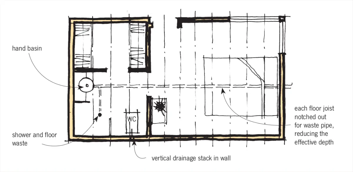
Fixing the bouncy floor in the bedroom was a major exercise as it involved taking up the entire floor in both the bedroom and adjacent ensuite bathroom (see Figure 2). The waste pipe running through the floor space was removed and a ceiling bulkhead was created in the space below the bathroom through which the waste pipe could be routed before discharging to an existing vertical drainage stack.
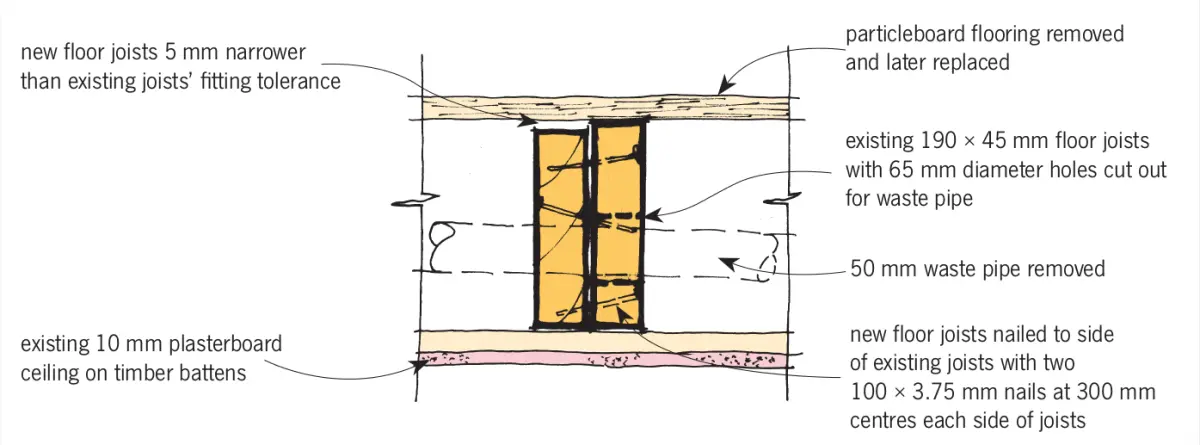
Joists were checked for sagging and propped from below where necessary to remove any sag. All joists were then strengthened by attaching new joists, cut 5 mm narrower than the existing to allow for a fitting tolerance, to the sides of the existing joists and fixed with two 100 × 3.75 mm nails at 300 mm centres on each side of the joists (see Figure 3). New flooring was then installed.
Design for services early
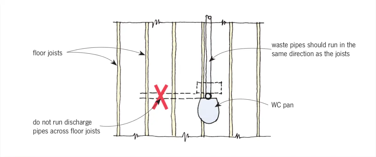
The lesson from this is that services should always be considered at the design stage of a building project. Although plumbing and drainage pipes can be installed underneath the floor joists of a ground level suspended timber floor, waste pipes under the first floor need to be carefully integrated within the building structure. Ideally they should be run parallel with the joists to avoid the need for drilling and notching (see Figure 4). To do this, there must be sufficient depth between the floor and ceiling to accommodate:
- the fall required in the pipe
- the diameter of the pipe
- any bends required in the pipe
- the notch and drill limits of NZS 3604:1999 unless specifically engineered.
Where waste pipes pass through the suspended floor structure, there must be sufficient joist depth to allow the drilling or notching without compromising structural performance – generally this means the floor will need to be specifically designed. Using an open web proprietary floor joist is one solution that allows pipes to be run across the floor structure without the need for drilling or notching.
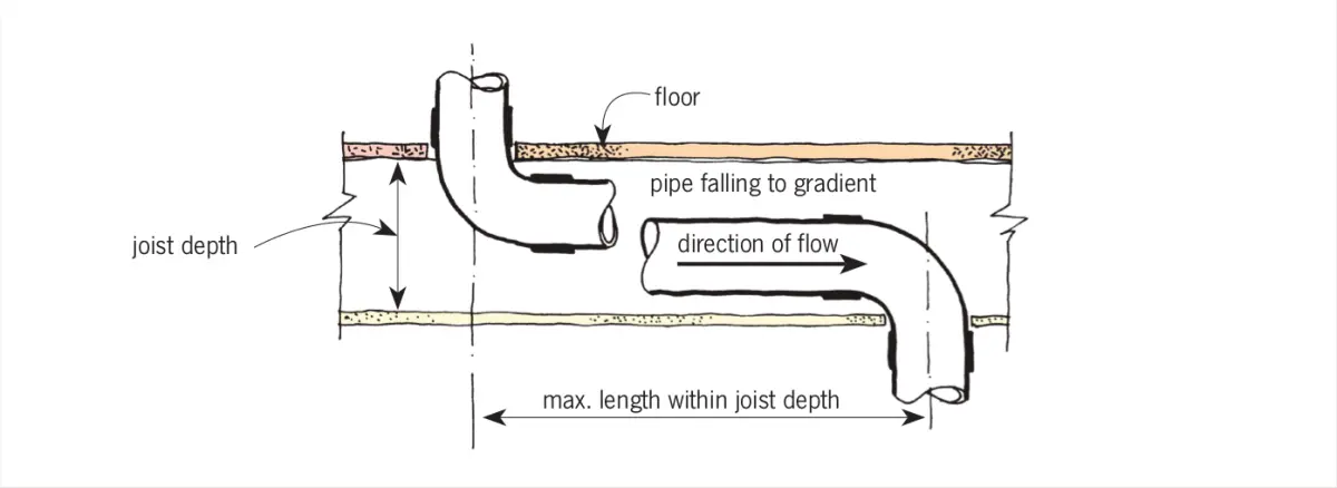
Figure 5 shows how pipe diameters, gradients and bends should be considered and incorporated. Holes must not be drilled through joists unless they are specifically designed and approved.
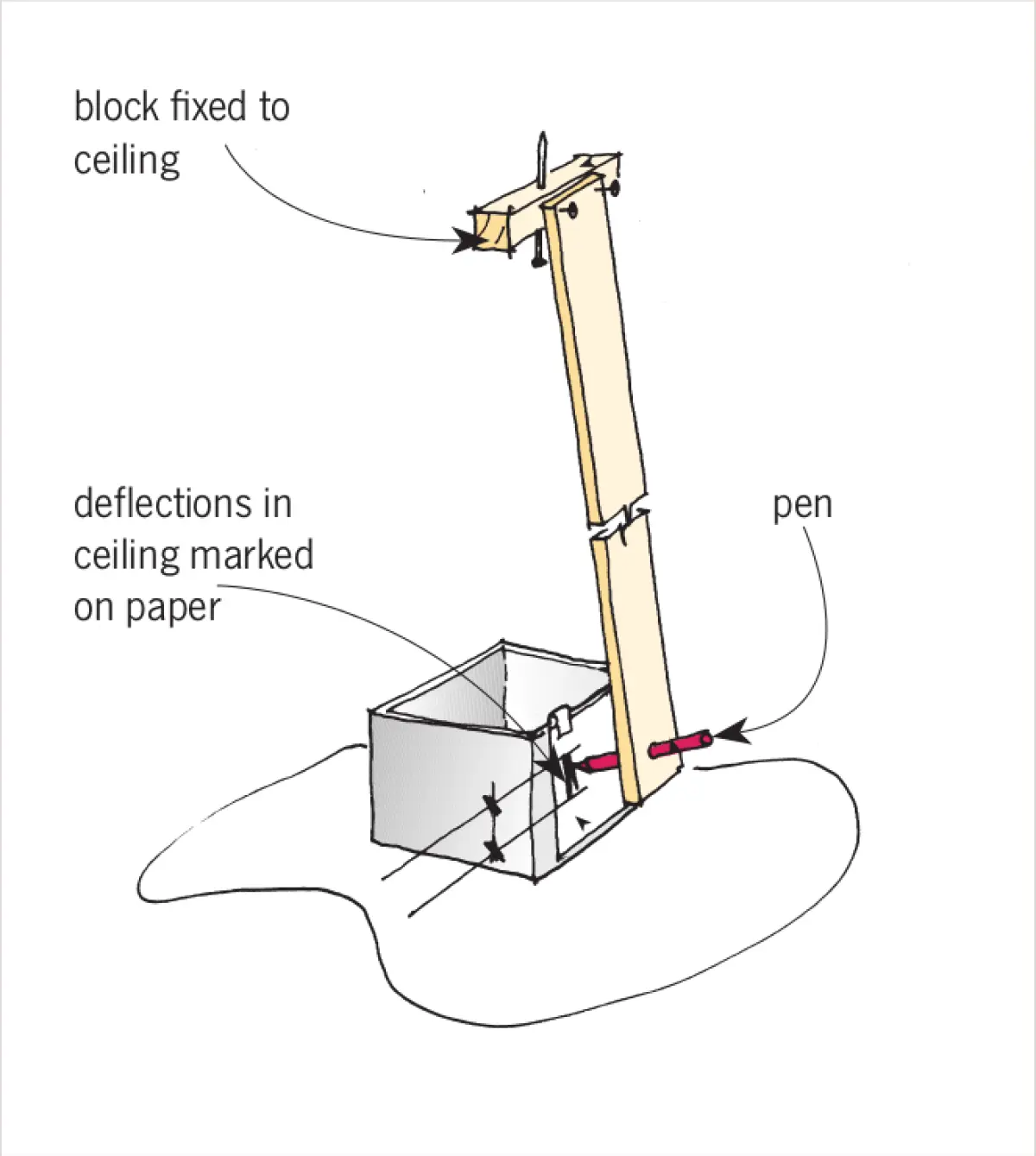
MEASURING FLOOR DEFLECTION
The deflection of a bouncy floor can easily be measured by fixing a batten to the ceiling below the floor at the greatest span of the floor joists. Attach a marking pen at the other end (see Figure 6). Paper or a vertical marking surface is placed where the marking pen hangs down. As the floor and ceiling above deflects, the range of vertical movement will be transferred onto the paper or marking surface.