


In H1/AS1 6th edition, Appendix E covers the thermal resistance of slab-on-ground floors. The Appendix includes tables of construction R-value tables for selected slab-on-ground floor scenarios. Some of these scenarios include the specification of vertical slab edge R1.0 insulation.
Raising building energy efficiency
Increasing the thermal resistance of slab-on-ground reinforced concrete floors has traditionally been addressed by the application of underslab polystyrene insulation either by insulating under the perimeter of the slab – 1.2 m from the edge – or by insulating under the entire slab footprint.
Addressing heat loss from the slab
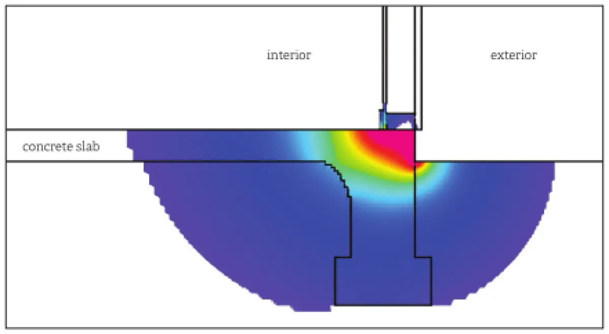
However, this does not address the heat loss from the slab that occurs at the external vertical floor slab/foundation surface. As seen in Figure 1, the greatest pathway of heat loss in an uninsulated floor slab is horizontally in the plane of the slab, especially adjacent to the bottom plate of the external perimeter wall framing. Note that this diagram does not show the actual temperatures but shows the flux or flow rates of warmth or heat escaping from the slab.
BRANZ scientists have confirmed that this is by far the greatest point of heat loss from a concrete slab-on-ground floor. The good news is that this remains a relatively accessible surface to insulate. The rigid insulation material can be attached to the inner face of the formwork prior to pouring the foundation and floor slab or can be applied to the bare vertical face of the foundation/slab edge after the formwork has been removed.
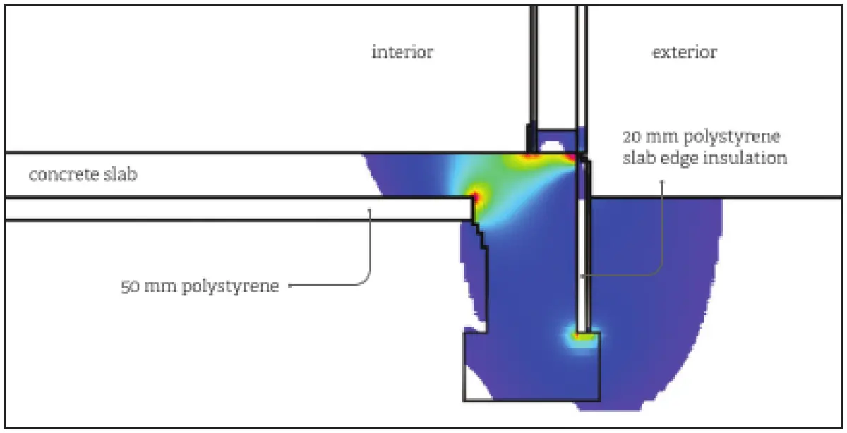
The other good news is that the insulation R-value to essentially prevent this heat loss is surprisingly low – approximately R1.0 – and this can be achieved with polystyrene insulation with thickness as little as 20–25 mm (see Figure 2). Designers and installers should note that the insulation should preferably be a minimum of XPS polystyrene, which is far more durable than EPS polystyrene and less susceptible to water absorption.
Proprietary products available
Several proprietary products coming on the market provide specifically designed concrete slab edge insulation. Be aware that some proposed products are rudimentary – for example, without protective coatings, so these must be applied in situ – while others are well designed and manufactured and perform well.
Any exposed polystyrene insulation applied to concrete slab edges must also be encapsulated to provide protection from moisture, UV degradation from sunlight and impact damage. If the protective layer is applied in situ, the most used method is an application of a layer of cement or acrylic-based reinforced plaster coated with a high-build or elastomeric type paint finish.
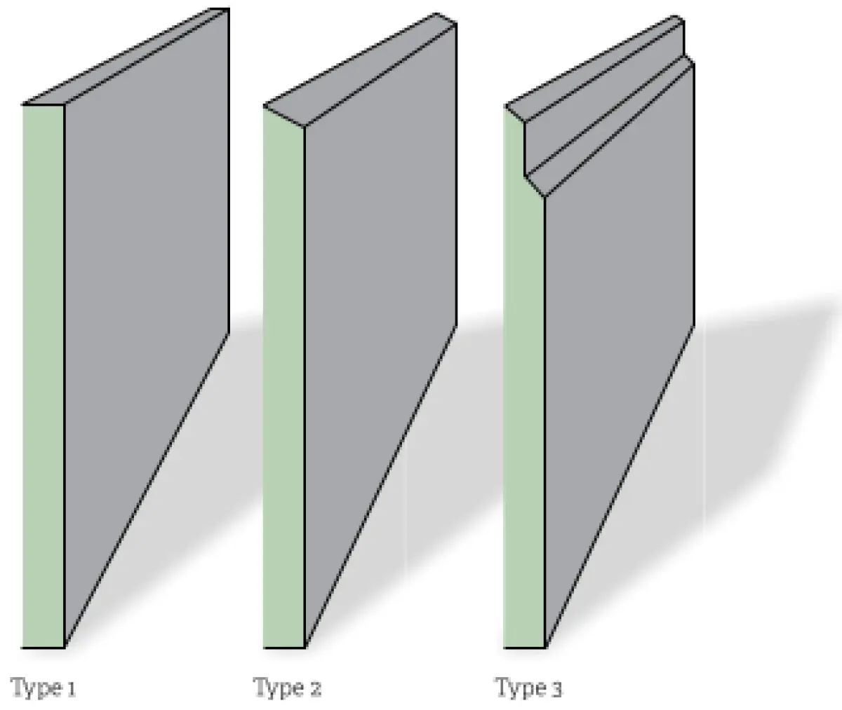
The alternative option is to use a proprietary prefinished slab edge insulation product. Figure 3 illustrates some of the most useful and commonly utilised prefinished slab edge insulation profiles – in this case, with factory applied protective plaster finish. The best options available use specialised reinforcing to the impact-resistant plaster layer, and some are kiln dried during the factory-applied finishing process to create a uniform, high-performance product.
It is recommended that a waterproof weathertight membrane or sealer coat is applied to the concrete foundation/slab edge prior to fixing of the insulation material – usually with adhesive plaster. Installation should be undertaken by informed and competent installers, preferably professional plasterers. A final overcoat of high-build waterproof paint is recommended.
Considering what profile to use
The profiles in Figure 3 are applicable to different situations often encountered at the slab/wall junction. Type 1 would be used where a 140 mm bottom wall plate can cantilever out beyond the slab edge and the insulation can be offered up flush to the underside of the bottom plate. Type 2 would be used where there is less space to manoeuvre, and a Z flashing would be installed behind the cladding, across the bevel and slightly down the face of the insulation layer. Type 3 would be tucked up behind the cladding downstand but still allow space for air movement in the cavity-fixed cladding system.
Architects and designers will face different criteria for the design of this junction. The wall may have cavity or face-fixed cladding, or there may be aesthetic objectives to express the junction between the insulation and cladding surfaces or make them appear flush in the same plane. However configured, this application will become more common.
While it is not mandatory for H1 compliance, the inclusion of this insulation does provide a huge improvement in the thermal performance of any reinforced concrete slab-on-ground domestic construction. As the calculation method becomes part of the ‘go to’ H1 compliance pathway for most domestic residential construction, we will see more slab edge insulation used, and it will become the norm rather than the exception.