

NZS 3604:2011 Timber-framed buildings specifically identifies locations for holes and notches in joists, studs and plates but does not include rafters and ceiling joists. BRANZ suggests that the locations and restrictions for floor joists are also used for these members.
Joists and rafters
NZS 3604:2011 sets out restrictions for holes and notches in joists:
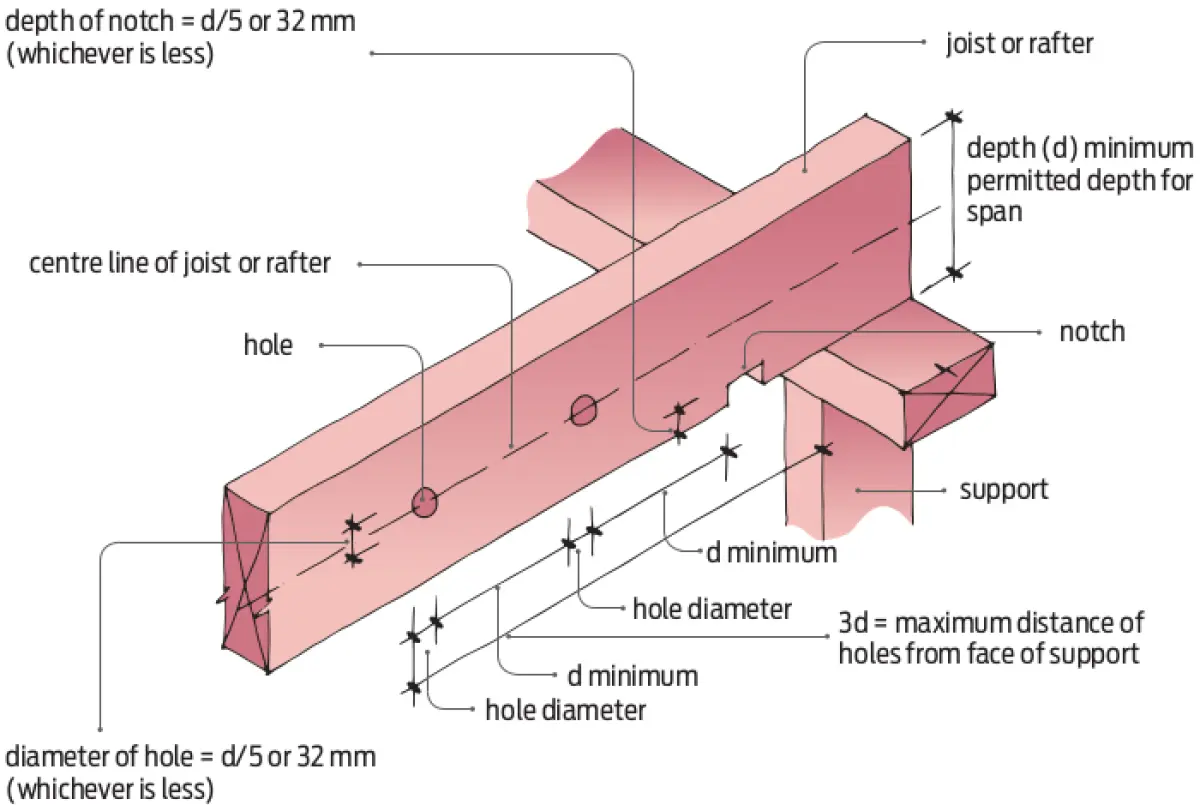
- The maximum allowable diameter of holes is one-fifth of the joist or rafter depth or 32 mm, whichever is the lesser (see Figure 1).
- The maximum allowable depth of notches is one fifth of the joist or rafter depth or 32 mm, whichever is less.
- Holes may only be located within a length measured from the face of a support that is no more than three times the depth of the joist or rafter.
- Holes and notches may not be closer to one another than the depth of the joist or rafter.
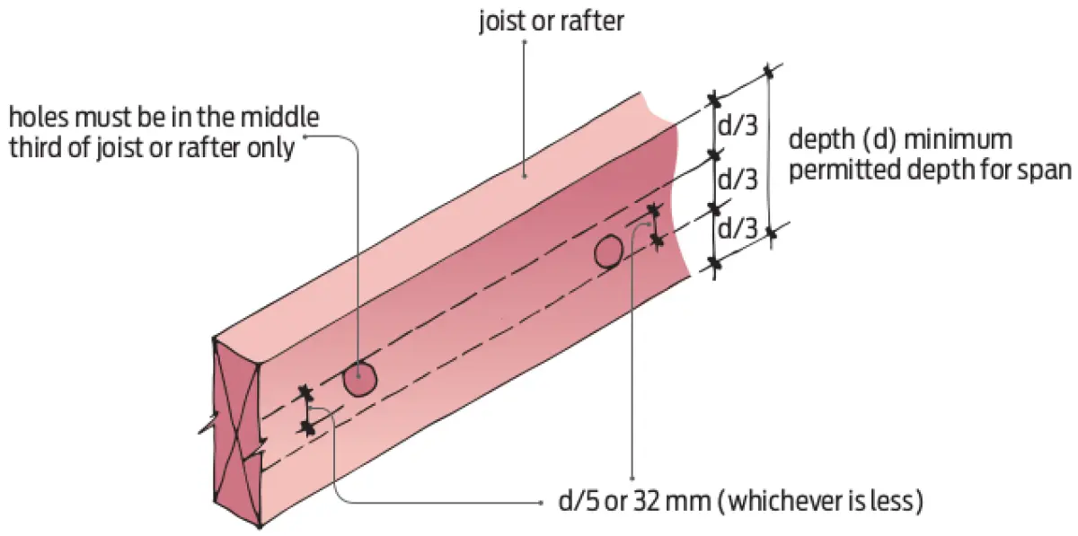
- Holes should be located in the middle third of the joist or rafter depth only (see Figure 2).
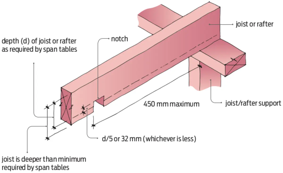
- Notches in joists and rafters may be located no more than 450 mm from the face of a support, unless the notch does not reduce the net depth of the joist to below that required by the span tables in NZS 3604:2011 (see Figure 3).
Cantilevered joists
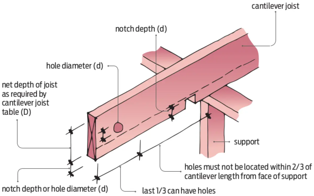
Holes or notches may be cut into cantilevered joists provided:
- the notch does not reduce the net depth of the joist to below that required by the span tables (see Figure 4), and
- holes are located in the outside third of the length of the cantilever measured from the face of the support.
Studs
Studs may have holes or notches cut into them with the following limitations:
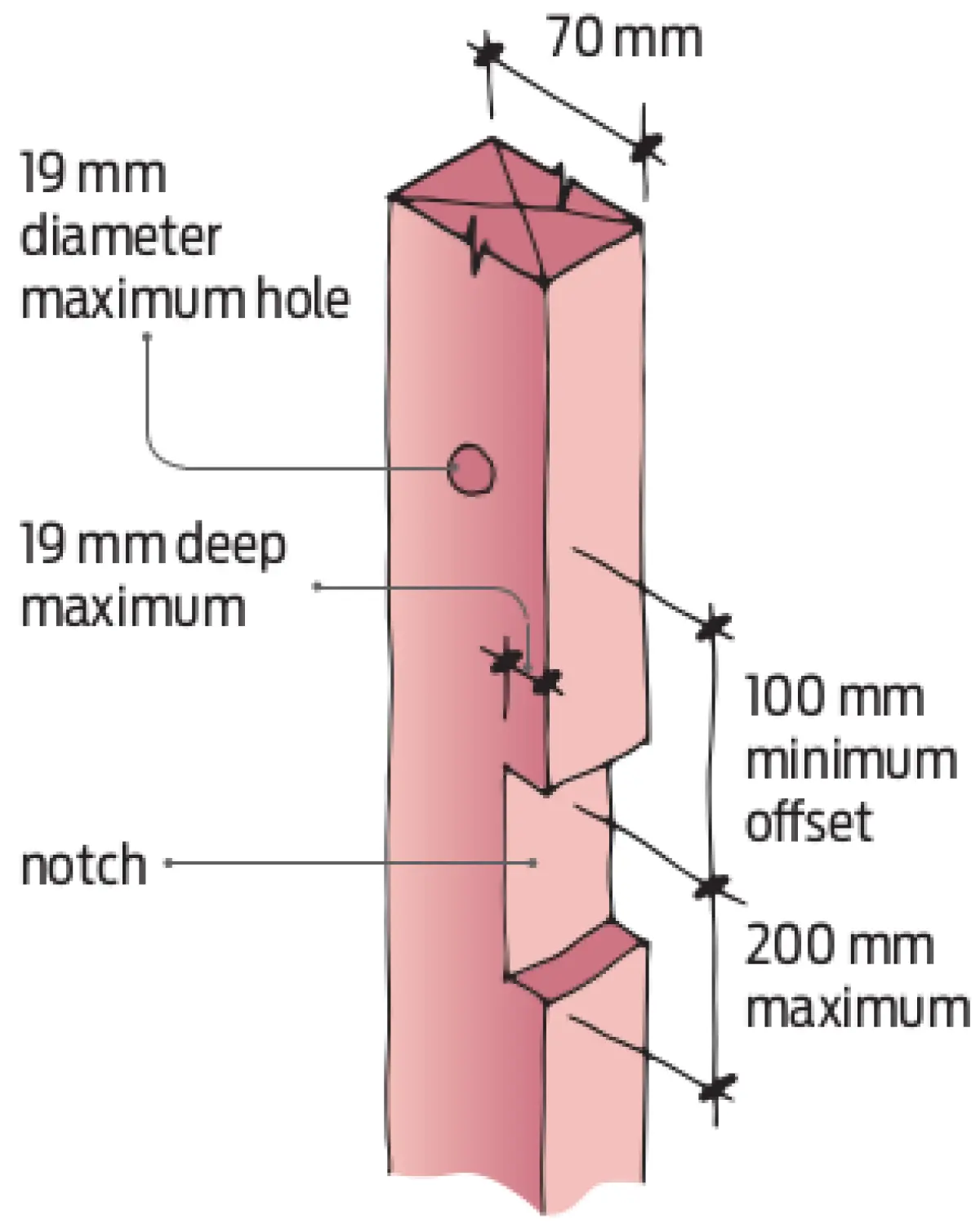
- In 70 mm deep studs, holes and notches should be no more than 19 mm in diameter or depth. The exception is that the depth of notches may be increased to 22 mm to fit diagonal metal bracing (see Figure 5).
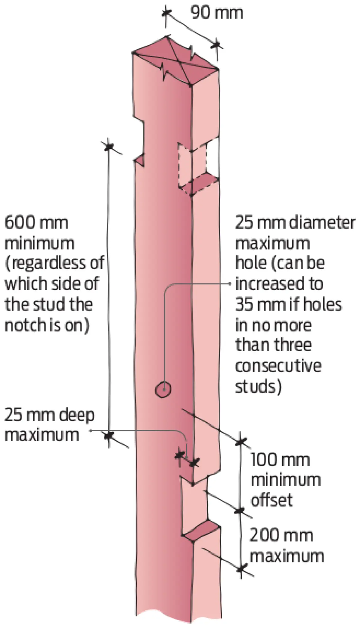
- In 90 mm deep studs, holes and notches should be no more than 25 mm in diameter or depth, except that the dimension may be increased to 35 mm where no more than three consecutive studs are drilled or notched (see Figure 6).
- For 70 mm and 90 mm deep studs, notches may be no more than 200 mm deep and should be vertically separated by at least 600 mm regardless of which side of the stud is notched.
- Holes and notches must be separated from one another by at least 100 mm.
- Holes in studs supporting brick veneer must be no closer than 50 mm from the outside face of the stud to allow sufficient depth for fixing brick ties.
- Trimming studs may not have any holes, notches, checks or cuts made in the middle third of the stud length regardless of stud dimension.
Top and bottom plates
Top and bottom plates sometimes require holes or notches. They generally have similar restrictions as for studs:
- In 70 mm deep top plates, holes may be no more than 19 mm in diameter, and notches may be no more than 19 mm deep and 200 mm long.
- In 90 mm deep top plates, holes may be no more than 25 mm in diameter, and notches may be no more than 25 mm deep and 200 mm long.
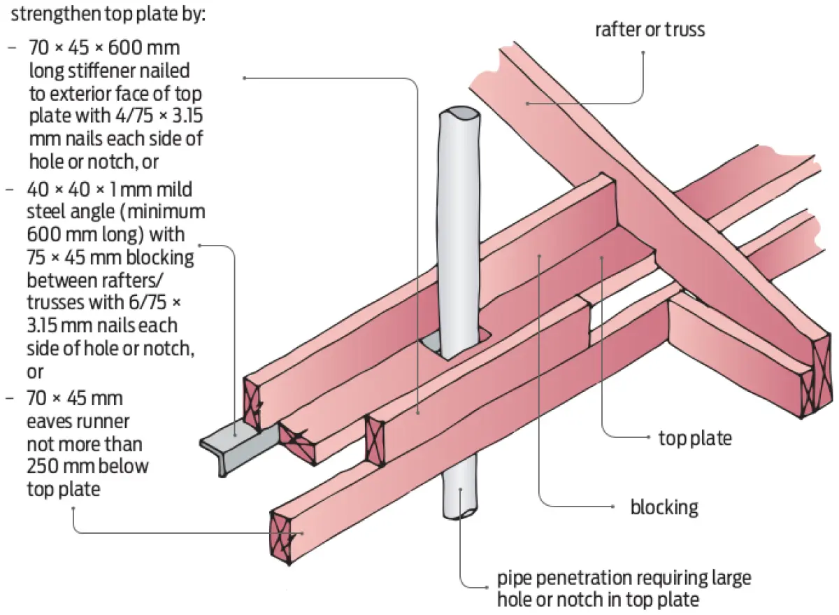
If the hole or notch required is larger than these dimensions, the top plate must be strengthened with extra timber and/or steel angle (see Figure 7).
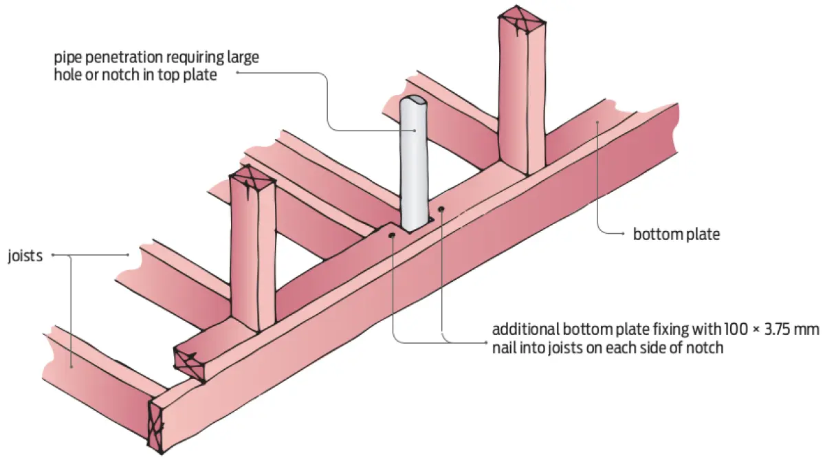
A hole or notch that is more than half of the width of the bottom plate must have additional 100 × 3.75 mm nail fixings on each side of the hole or notch (see Figure 8).