




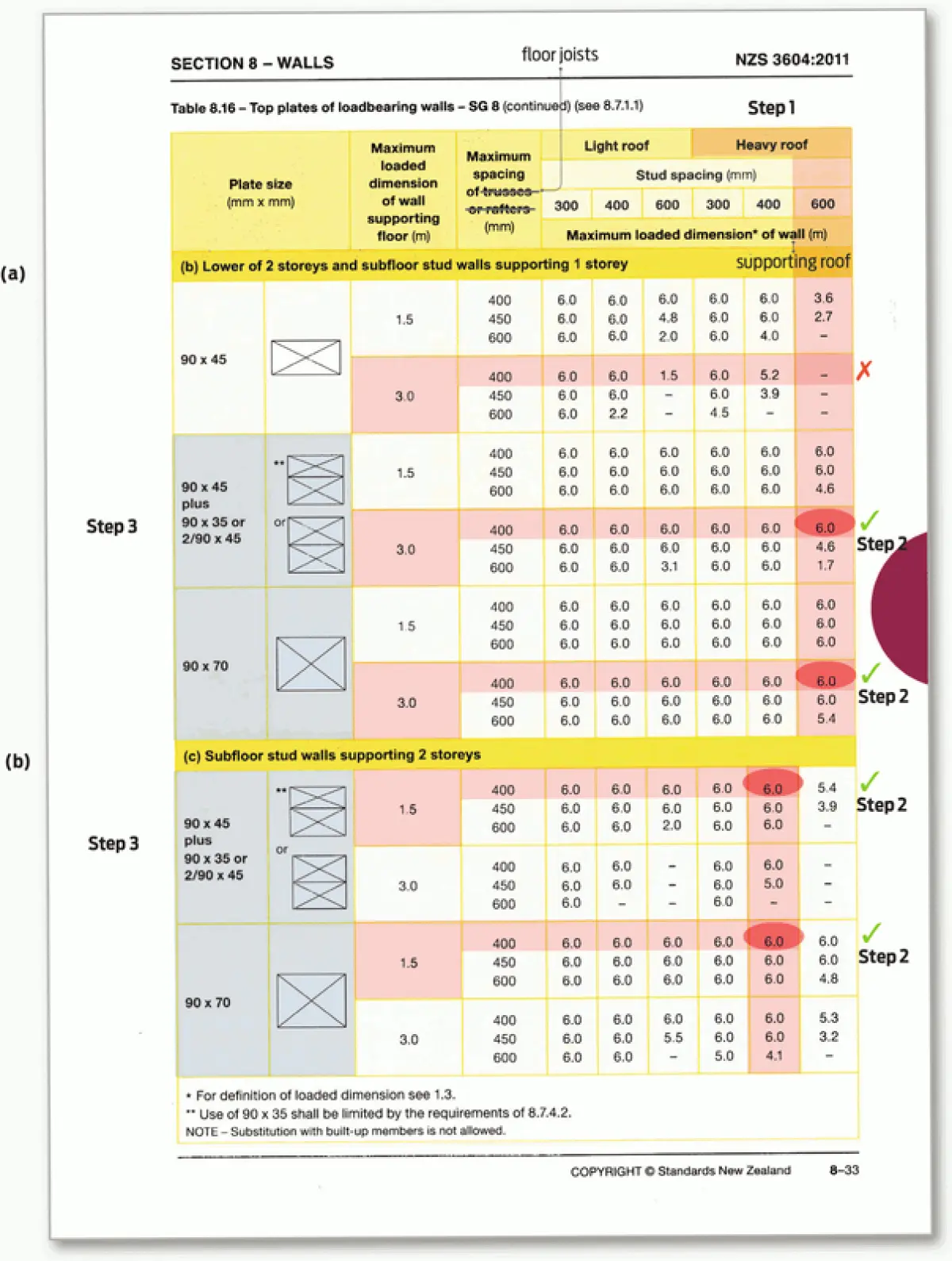
To correctly use NZS 3604:2011, it helps to first correct two column headings in Table 8.16(b):
● Change ‘Maximum spacing of trusses or rafters’ to ‘Maximum spacing of floor joists’.
● Maximum loaded dimension of wall’ should read ‘Maximum loaded dimension of wall supporting roof’.
Start with a question
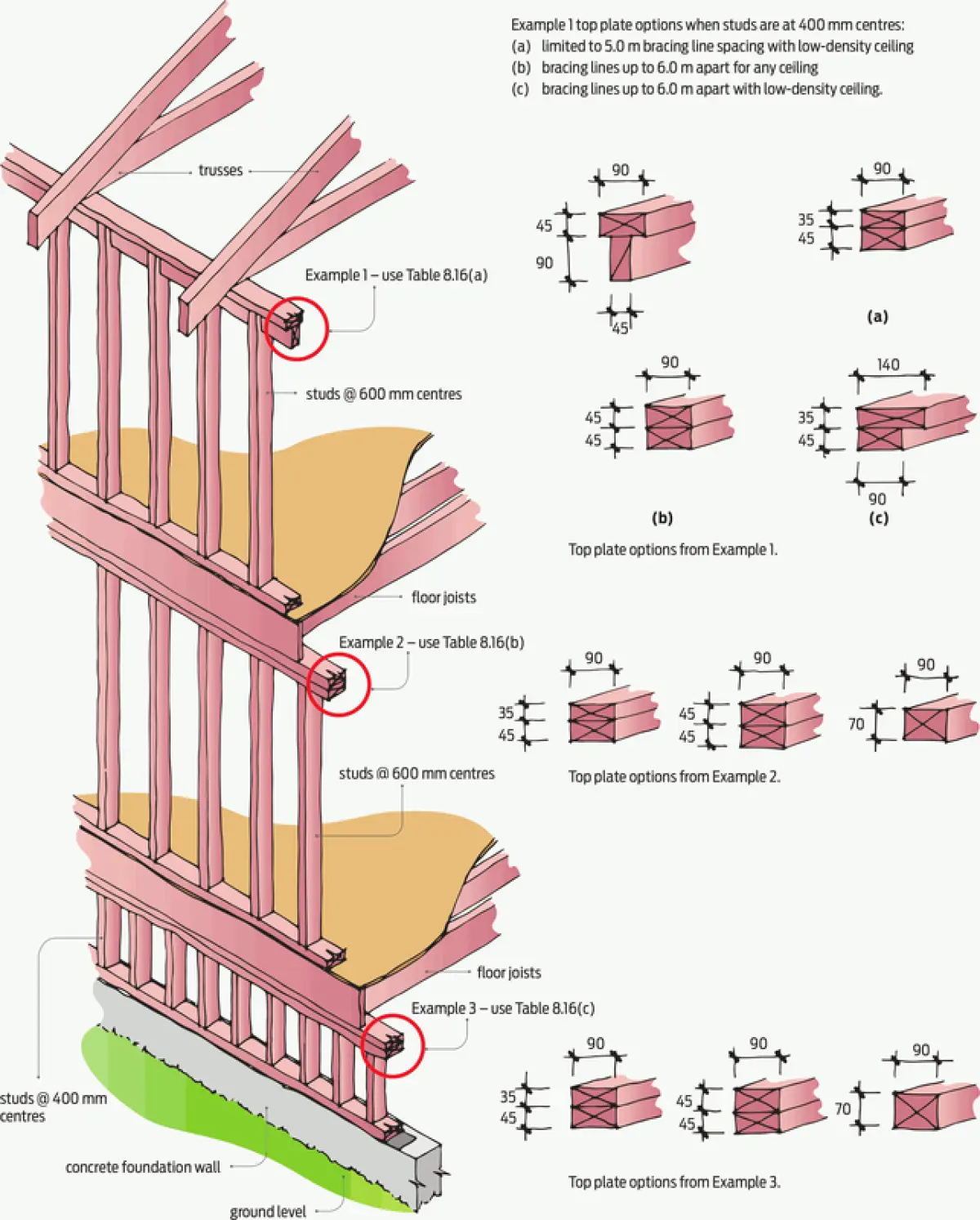
What does the top plate support (see Figure 1)? This leads to the correct part of Table 8.16 to use:
● Where the top plate supports the rafters or trusses of a single or top storey – use Table 8.16(a).
● Where the top plate supports the mid-floor of 2 storeys – use Table 8.16(b).
● Where the top plate is part of a subfloor frame supporting a single storey – use Table 8.16(b).
● Where the top plate is part of a subfloor frame supporting 2 storeys – use Table 8.16(c).
Other considerations
Limited substitution
Top plates can not be substituted with built-up members unless shown in Table 8.16. For example, where the table requires 90 × 70 mm, a built-up member of 2/90 × 35 mm is not permitted.
Positioned over studs
Table 8.16 doesn’t apply where rafters/trusses or floor joists are positioned directly over the studs below. In this situation, the top plate must be at least the same width as the studs and a minimum of 35 mm thick.
Bracing line maximum distance
Clause 8.7.4.2 requires a maximum distance of 5 m between bracing lines where the top plate is the boundary of a proposed ceiling and the ceiling is less than 600 kg/m3.
This can be extended up to 6 m when an additional 140 × 35 mm is added to the 90 × 45 mm top plate and fixed at 500 mm centres with either 2/100 × 3.75 mm hand-driven nails or 3/90 × 3.15 mm gun nails. This needs to be the same grade as the top plate.
Note: 10 mm standard plasterboard is about 700 kg/m3, so bracing lines up to 6 m would be allowed using the top plate options in Table 8.16,that is, 90 × 35 mm added to 90 × 45 mm.
Truss supports
Table 8.16 allows for some top plate selections to have a truss supported within 150 mm of the supporting studs. Alternatively, the truss/rafter can sit anywhere on the plate in relation to the studs. The following examples use ‘anywhere’.
Example 1 – Table 8.16(a)
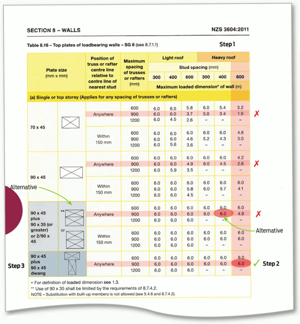
The first example is for a single-storey or upper storey frame supporting a roof, so Table 8.16(a) is used. The parameters are:
● heavy roof
● 600 mm stud spacing
● truss position is anywhere
● truss spacing is 900 mm
● loaded dimension of wall is 6 m.
Using Table 8.16(a), work through the steps (see Figure 2):
● Step 1 – Select the relevant column by choosing:
• heavy roof
• 600 mm stud spacing column.
● Step 2 – Select the relevant row(s) by looking at:
• the truss position of anywhere
• 900 mm truss spacing
• checking if these provide a loaded dimension of 6 m in the column selected in step 1.
● Step 3 – Read off the required top plate size in the first two columns of the selected row.
In this case, a 90 × 45 mm top plate is required with a 90 × 45 mm dwang under the top plate at the position of trusses or rafters. See NZS 3604:2011 Figure 8.13 for dwang fixings.
Alternatively, consider studs at 400 mm centres. This would require a double 90 × 45 mm top plate or a 90 × 45 mm with an additional 90 × 35 mm plate attached (fixed as referenced above). This option would require the 90 × 35 mm to be replaced with a 140 × 35 mm added to the top plate when bracing lines at right angles to the wall exceed 5 m spacing or if the ceiling is less than the 600 kg/m³ (standard 10 mm plasterboard is approximately 700 kg/m³).
Example 2 – Table 8.16(b)
The second example is for the lower of 2 storeys supporting a mid-floor or a subfloor stud wall supporting one storey. The parameters are:
● heavy roof
● stud spacing is 600 mm centres
● loaded dimension of wall supporting floor is 2.4 m
● floor joists at 400 mm centres
● loaded dimension of 6 m for the wall above the floor that is supporting the roof.
Using Table 8.16(b), work through the steps (see Figure 3(a)):
● Step 1 – Select the relevant column by choosing:
• heavy roof
• 600 mm stud spacing column.
● Step 2 – Select the relevant row(s) by looking at:
• loaded dimension of the wall supporting the floor, i.e. 2.4 m or more – choose 3 m
• maximum floor joist spacing of 400 mm
• checking if these provide a loaded dimension of 6 m in the column selected in step 1.
● Step 3 – Read off the required top plate size in the first two columns of the selected row(s). In this case, three options are available:
• 90 × 45 mm plus 90 × 45 mm
• 90 × 70 mm
• 90 × 45 mm plus 90 × 35 mm (this can only be used if the bracing lines at right angles to the walls are at 5 m centres or less).
Example 3 – Table 8.16(c)
In the final example, the top plate is in a subfloor wall supporting 2 storeys. The parameters are:
● heavy roof
● stud spacing is 400 mm centres
● loaded dimension of wall supporting the floor is 1.3 m
● joist spacing is 400 mm centres
● loaded dimension of wall supporting roof is 6 m.
Using Table 8.16(c), work through the steps (see Figure 3(b)):
● Step 1 – Select the relevant column by choosing:
• heavy roof
• 400 mm stud spacing column.
● Step 2 – Select the relevant row(s) by looking at:
• loaded dimension, i.e. 1.3 m or more – choose 1.5 m
• maximum floor joist spacing of 400 mm
• checking if these provide a loaded dimension of 6 m in the column selected in step 1.
● Step 3 – Read off the required top plate size in the first two columns of the selected row(s). In this case three options are available:
• 90 × 45 mm plus 90 × 45 mm
• 90 × 70 mm
• 90 × 45 mm plus 90 × 35 mm – this can be used as the bracing lines in subfloors are a maximum of 5 m centres and would therefore comply with the requirements of clause 8.7.4.2.