

We continue the Build series on roof-to-wall junction details not included in Acceptable Solution E2/AS1 to the New Zealand Building Code clause E2 External moisture.
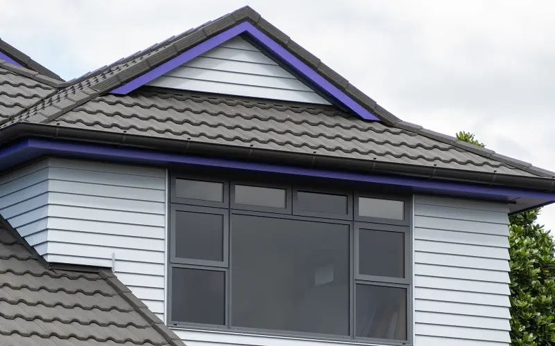
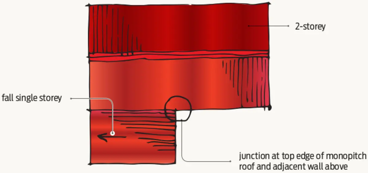
This detail occurs at the junction between the top edge of a monopitch roof and an adjacent wall above (see Figure 1).
Steps for installation
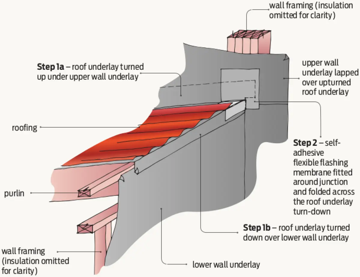
Figures 2–5 illustrate the steps of the construction sequence for the detail with a sheet cladding material over a drained and vented cavity.
Step 1: Install roof and wall underlay over framing. Turn the roof underlay up under adjacent wall underlay (1a) and overlap the lower wall underlay (1b).
Step 2: Fit a self-adhesive, flexible flashing membrane over the junction. Cut and fold a section of the membrane across the roof underlay turn-down.
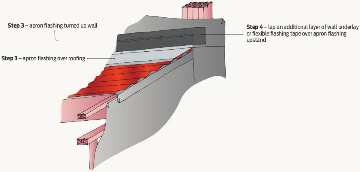
Step 3: Install apron flashing over the roofing with upstand over upper wall underlay. Apron flashing to have at least the minimum upstand height and roof cover required by E2/AS1.
Step 4: Lap an additional layer of wall underlay or fix self-adhesive, flexible flashing tape over the apron flashing upstand.
Step 5: Install cavity battens to lower wall.
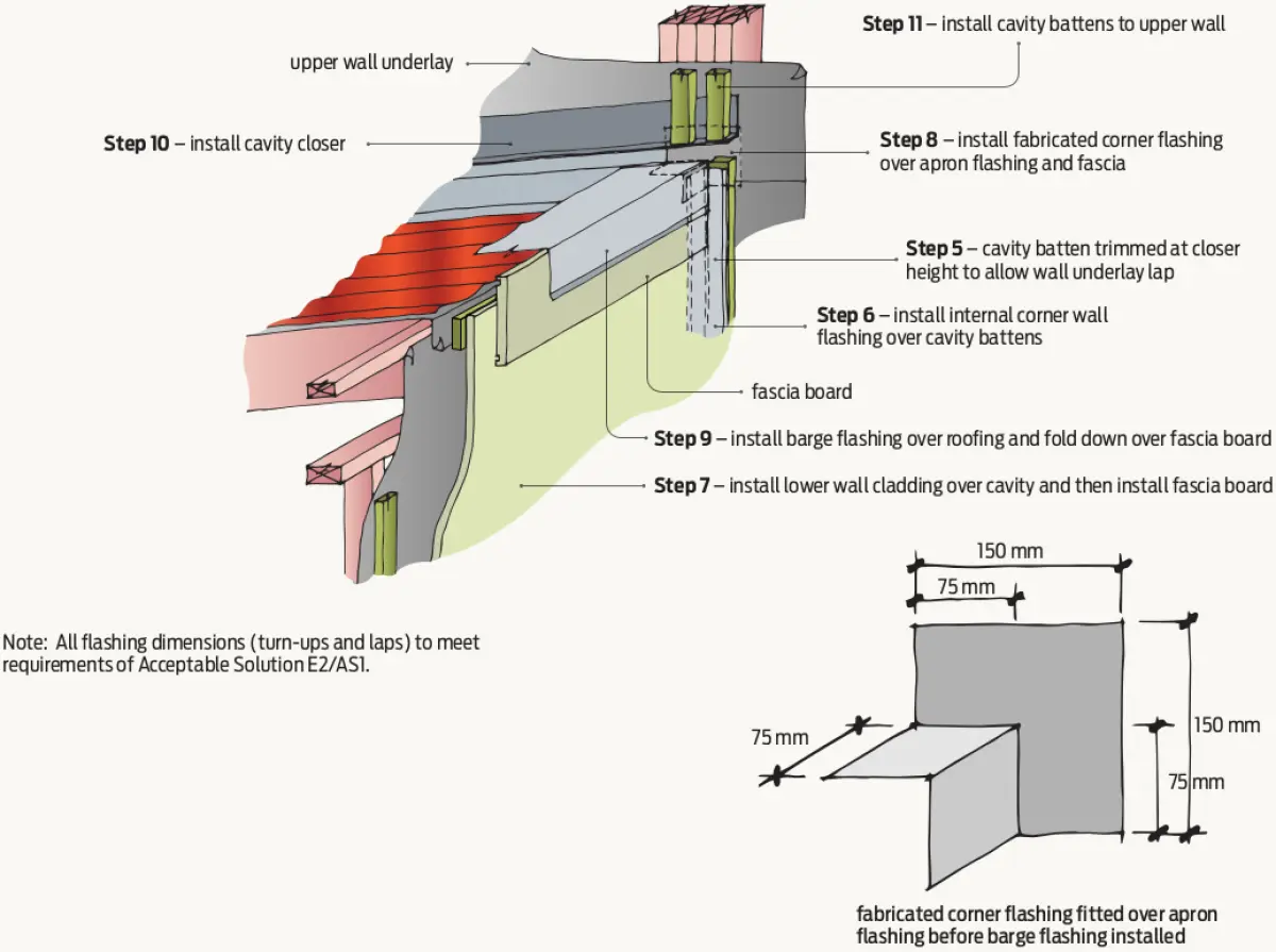
Step 6: Install internal corner wall flashing over cavity battens on the lower wall. The corner flashing must end behind the barge flashing.
Step 7: Install lower wall cladding over cavity battens and then install fascia board.
Step 8: Install fabricated corner flashing over apron flashing and fascia.
Step 9: Install the barge flashing over the roofing and fascia board.
Step 10: Install cavity closer above apron flashing maintaining the minimum gap required by E2/AS1 (generally 35 mm).
Step 11: Install cavity battens to upper wall.
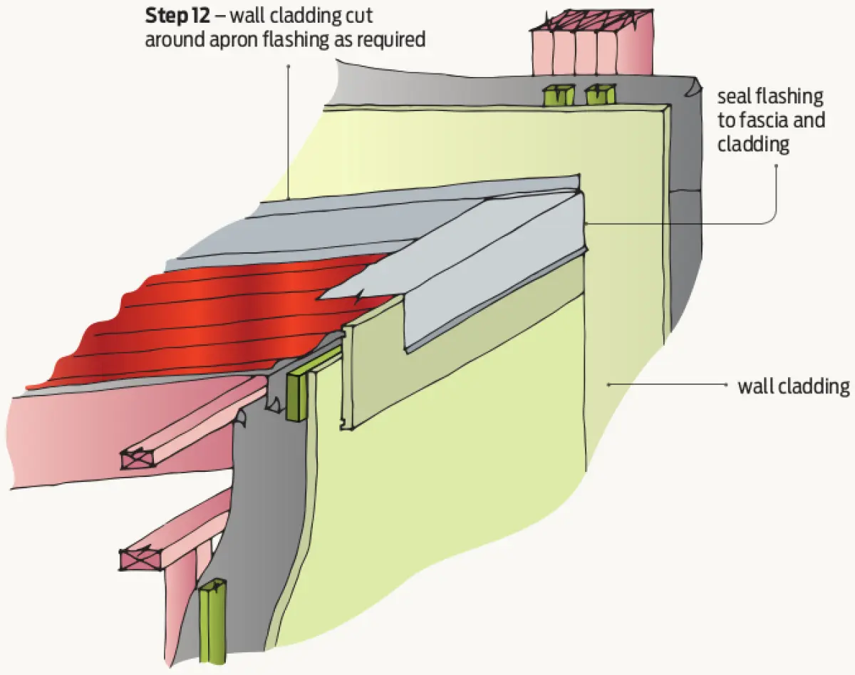
Step 12: Install cladding over the cavity battens cutting the cladding to fit around the apron flashing as required.
Some specifics from E2/AS1
Specific requirements in Acceptable Solution E2/AS1 include that there must be:
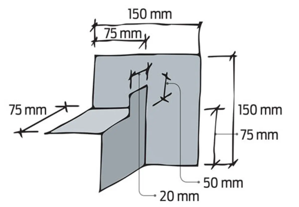
- a 75 mm minimum wall cladding cover over the upstand
- a gap between the wall cladding and the roofing as given in E2/AS1 Table 7
- roof flashing cover over the roofing as per E2/AS1 Table 7, depending on wind zone and roof pitch.
Footnote: Letter to editor in Build 166
Don’t forget the stop-end
DEAR BUILD,
I am writing to point out a technical defect in the article Roof-to-wall junction detail (Build 165, pages 31–33). As drawn, the details do not close off the cavity to water entry blown by wind up the slope of the roof on the apron flashing.
The fabricated corner flashing needs a stop-end, with the stop-end 35 mm minimum high up to the bottom of the cladding, then cut back to also close off the cavity up to the top of the flashings. The cladding cavity closer would then butt into the stop-end, or the stop-end could be 50 mm high and the cavity closer could pass over the top of it. The cladding beyond the roof would then be sealed to the stop-end and the corner flashing at the vertical joint between the two.
The junctions are very complicated, and it is important to get them right!
LEIGH MARSHALL : AUCKLAND
BRANZ comment
Thank you for your feedback. Adding a stop-end as you suggest is a good idea to add another layer of protection.
It is important that adding a stop-end does not introduce additional weak points, such as needing to notch in a cladding or other material to accommodate it. Our revised fabricated corner flashing incorporates a simple stop-end to stop water passing over the top of the detail while not impacting on the cladding above.