

Correctly installed flashings are essential to ensuring weathertightness, but in some locations, detailing and installation can be tricky. This is when it is necessary to achieve a detail that not only keeps out moisture and meets the requirements of Acceptable Solution E2/AS1 but that is also durable and aesthetically pleasing.
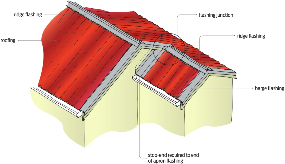
One such detail is the junction between the main gable of a building and the ridge from a smaller gable, often a garage (see Figure 1).
Sequence of assembly – no eave
The sequence of assembly of flashing such a junction is critical to achieving a weathertight detail.
Figures 2(a)–(c) show the sequence for flashing the junction between the gable and ridge where there is no eave.
Figure 3 shows the shapes of each of the flashings and how they should be folded.
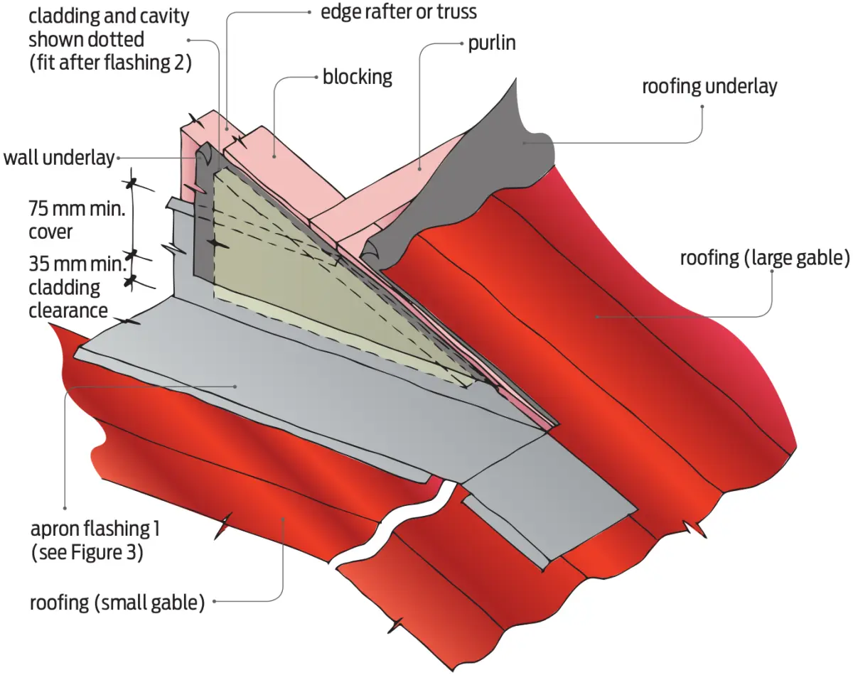
Step 1
Flashing 1 is a typical apron roof flashing. The flashing upstand is carried up under the cladding and wall underlay and the flashing apron is extended over the ridge of the smaller gable (see Figure 2(a)).
Step 2
Flashing 2 covers both the apron flashing upstand and the wall underlay. It is folded over the large gable roof and the apron flashing and also extended over the ridge of the smaller gable (see Figure 2(b)).
Step 3
Fit a butyl rubber patch over flashing 2 (see Figure 2(b)).
Step 4
A ridge flashing is fitted over the smaller gable ridge butting up to the wall cladding, and the bargeboard is installed over the ridge. Flashing 3 is a standard barge flashing that, on the large gable roof, extends beyond the ridgeline of the smaller gable and aligns with the bottom edge of the ridge flashing (see Figure 2(c)).
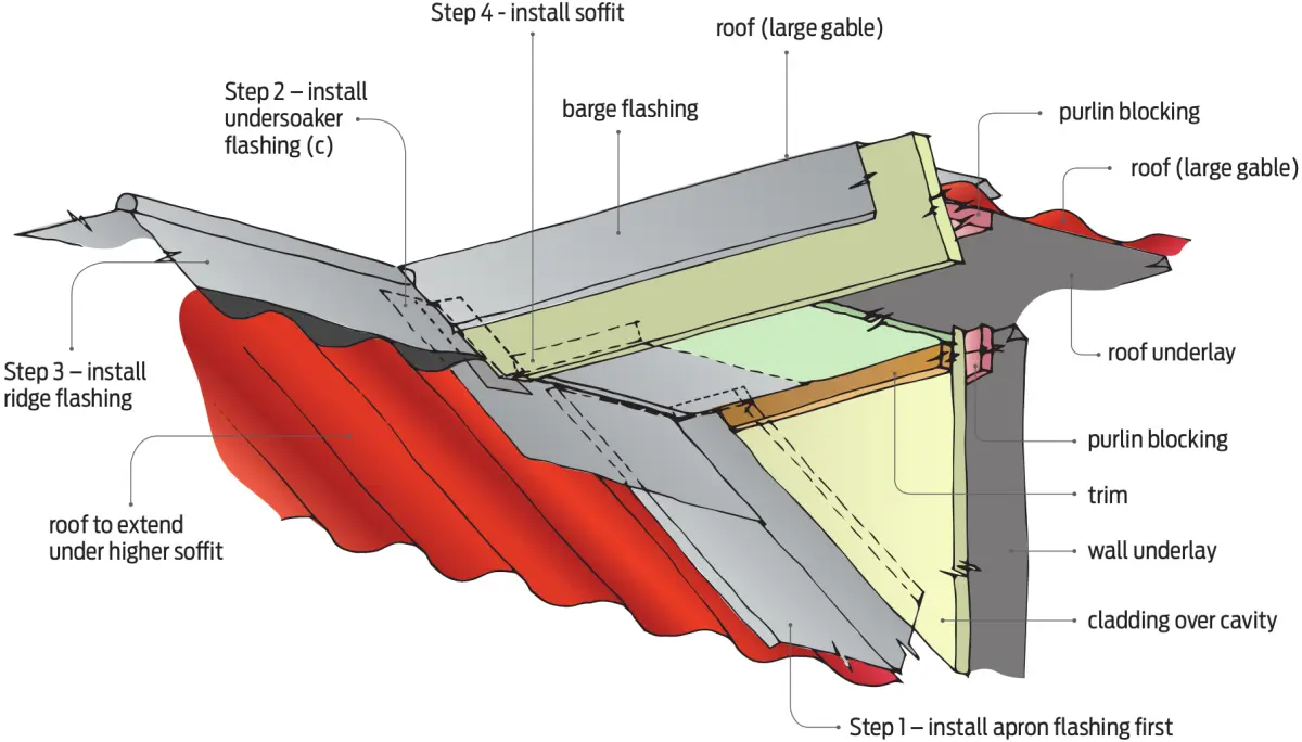
Roof junction with an eave
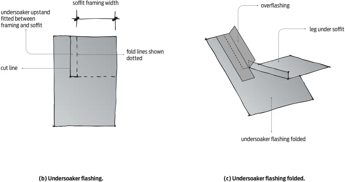
Where there is an eave at the junction between the two gables, the apron and barge flashings are fitted in the same way. However, an undersoaker flashing is required over the soffit, apron flashing and roof (see Figure 4).