

Different specialists will do the design, the cage fabrication and the on-site installations of reinforcing steel, but it is valuable for everyone to have enough knowledge to ensure things are being done correctly. What if site adjustments have to be made. Can the steel be rebent or welded? How sharp can a main bar be bent? What about a stirrup? Does galvanising affect anything? It all depends what steel is being used and why.
| Grade 500E MA | Grade 500E QT | Grade 300E | |
|---|---|---|---|
| Initial bending (to NZS 3101) | Comply with NZS 3109 (Use proper tools. Prevent notching. Conform to minimum bend diameters.) Bend at temperatures above 5°C. | ||
| Rebending or straightening (cold) | Not permitted | Not permitted | Avoid |
| Butt welding | Avoid | Not permitted | Avoid |
| Lap welding | Avoid | Not permitted | Avoid |
| Tack welding (bars critical to structural performance) | Not permitted | Not permitted | Not permitted |
| Galvanising | Check with supplier | Check with supplier | Check with supplier |
| Threading | Proceed with care | Avoid | Proceed with care |
Reinforcing grade 300 or 500
Grade 300 reinforcing steel is commonly used on residential properties and for some applications on other larger projects. If, for instance, the construction is being built in accordance with NZS 3604:1999 Timber framed buildings and a D12 bar is called up, then it should be grade 300E complying with AS/NZS 4671 Steel reinforcing materials as directed by clause 2.5.
However, engineers often want to get more performance from the concrete components being reinforced. This leads them to specify reinforcing steel that has a higher yield strength (even though it does have lower ductility and toughness). Commonly this is known as ‘high tensile’ reinforcing and is now required to be grade 500E (with a yield strength of 500–600 MPa).
Treatment gives MA or QT
To get this higher yield strength, the steel is treated in either of two ways during manufacture. One way is to add exotic micro-alloy trace elements like titanium and vanadium, which provide the added strength. This steel (usually labelled MA) must then be strictly treated in accordance with the manufacturer’s requirements and NZS 3101 Concrete structures and NZS 3109 Concrete construction. For instance, it cannot be rebent cold, and any hot rebending must be done under stricter control and supervision than is normally available on site (see Table 1).
The second and more common process is that the steel is quenched and tempered during manufacture resulting in the steel being stronger and less ductile on the outside and gradually reducing in yield to a more ductile inner core. This is a more efficient process, producing a steel (usually labelled QT or QTR) that must never be rebent hot or cold and cannot be welded because it de-tempers the steel. Cutting a thread on the end of this steel should be avoided as it cuts into the higher yield steel, having a bigger effect than cutting a thread on the micro-alloyed steel.
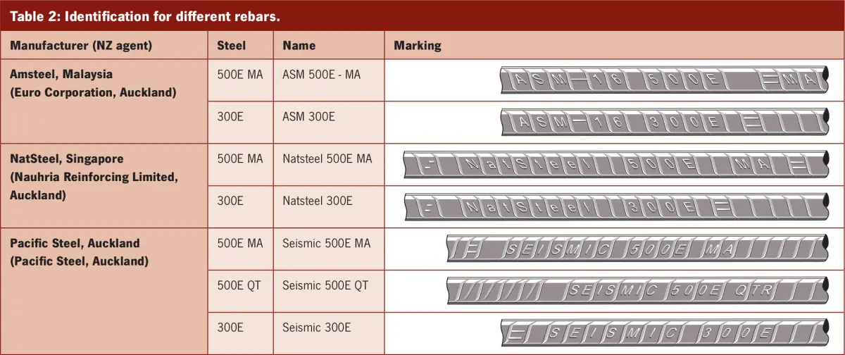
Identifying the rebar
Having three reinforcing steels each with different performance characteristics means that it is important to be able to clearly identify each one. This has, on occasion, been shown to be difficult, when imported steels have been introduced to our market.
The Department of Building and Housing Practice Advisory 11 Market Update (Dec 2009) has the markings of three known products being used in New Zealand (see Table 2). It advises designers and builders to call for testing of product samples to provide evidence of compliance with AS/NZS 4671:2001 for particular jobs.
Getting the right laps…
Laps are often required to achieve continuous lengths or to allow for tolerance on bar lengths. The lap transfers the force in one bar to the lapping bar through the surrounding concrete. Laps are usually formed by tying the bars together before the concrete is placed.
This force transfer takes place through the surface area in contact with the concrete, that is, bar perimeter × length. Tables 3 and 4 show the required lap length for each bar diameter and grade. There are other factors that are dependent on the application, but for small-scale residential walls and footings using concrete or masonry, these tables can be used to summarise the requirements.
| Diameter | Grade 300 laps (mm) | Grade 500 laps (mm) |
|---|---|---|
| R10 (plain round) | 350 (with hooks) | – |
| D10 (deformed) | 350 | 550 |
| D12 | 400 | 650 |
| D16 | 500 | 850 |
| Diameter | Grade 300 laps (mm) | Grade 500 laps (mm) |
|---|---|---|
| R10 (plain round) | 800 | – |
| D10 (deformed) | 400 | 700 |
| D12 | 480 | 840 |
| D16 | 640 | 1,120 |
…and the correct bends
It is important with reinforcing steel to get the bends correct. This was particularly an issue when a range of site-bending equipment was imported without different sized mandrels for bending different sized bar to different radii.
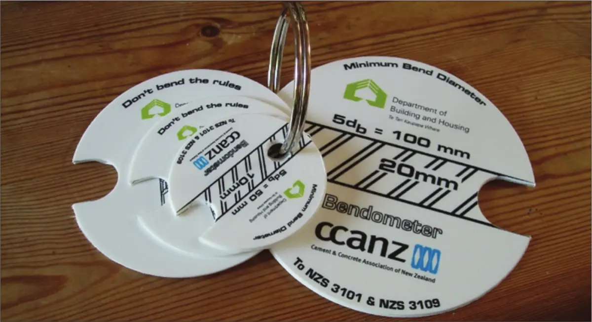
Deformed and round bars are bent to differing radii, and as the sizes increase, so does the required radius (see Table 5).
To assist in gauging that the bends are correct and in accordance with NZS 3109, the Department of Building and Housing produced a handy Bendometer tool for measuring this (see Figure 1).
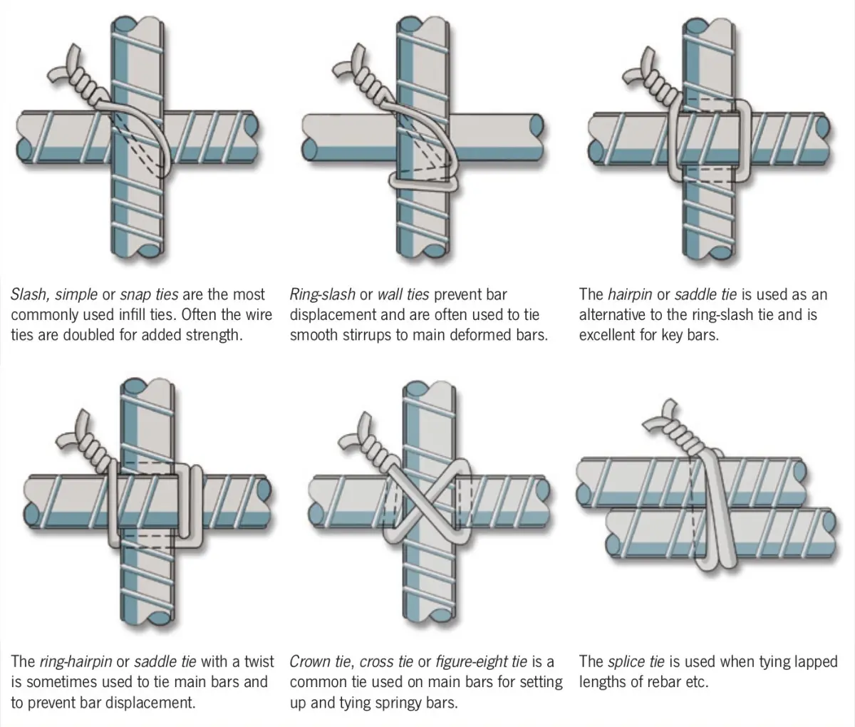
Tying it all together
The final thing inspectors will be looking for, is that the cages are tied well and supported correctly (see Figure 2).
The reinforcing steel should always have at least 50 mm cover and 75 mm when spaced off bare ground, unless a more thorough determination of cover is undertaken in accordance with NZS 3101. There must be enough ‘chairs’ or supports to ensure that the steel doesn’t sag into that cover space.