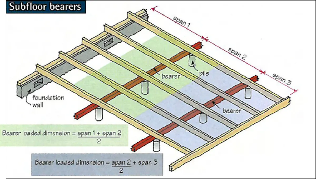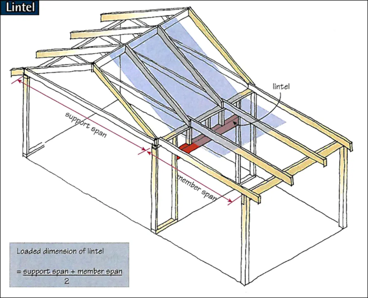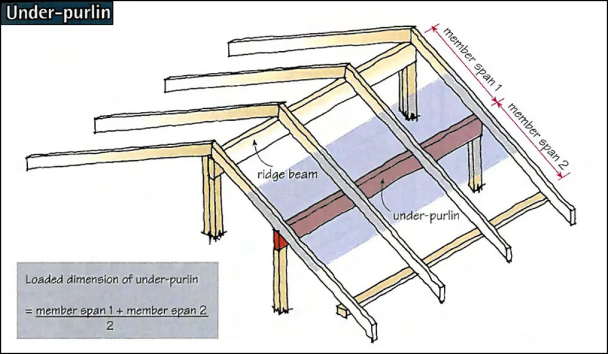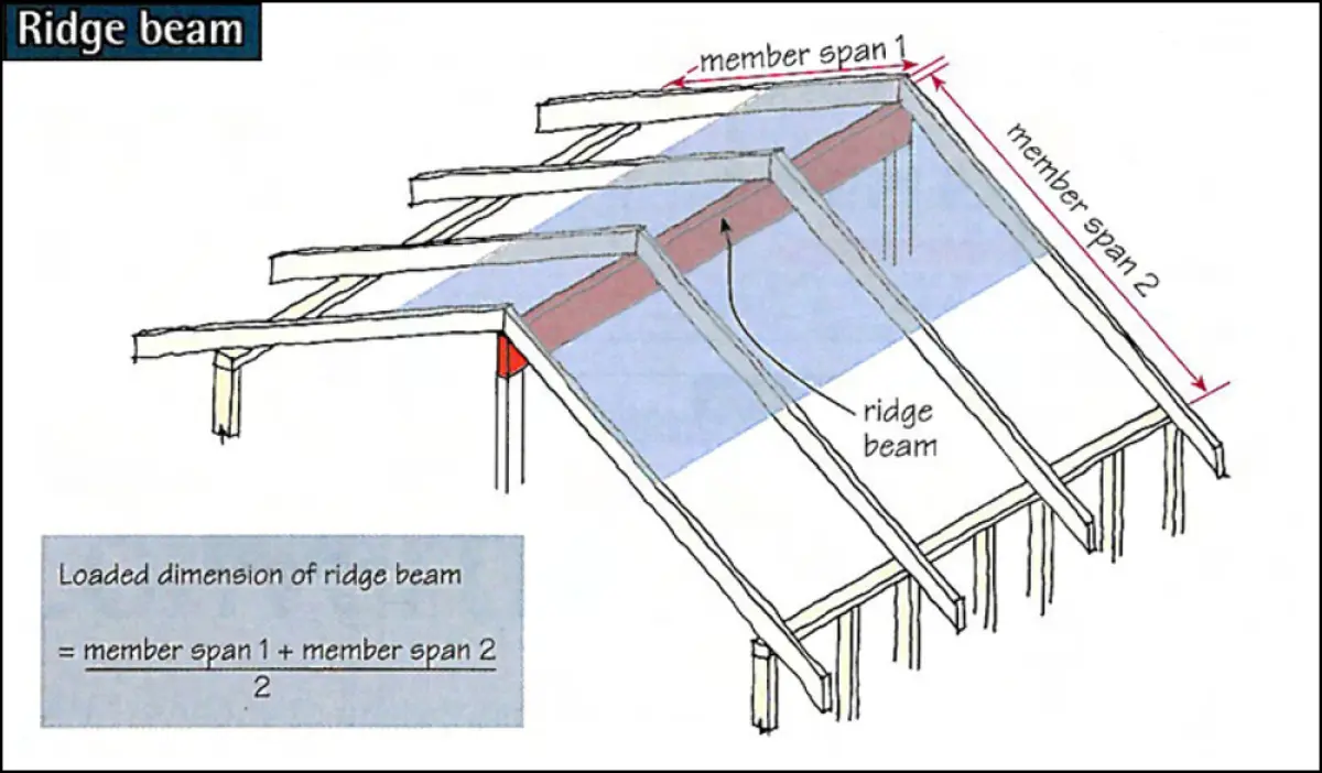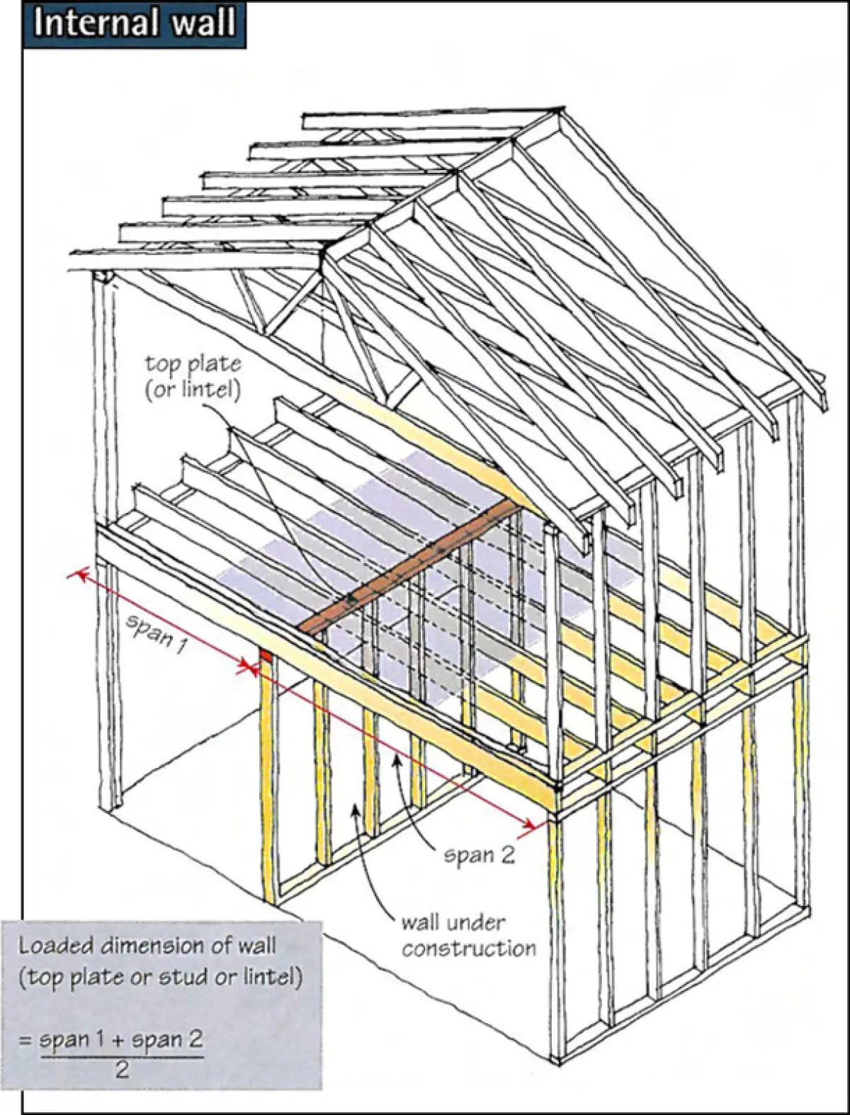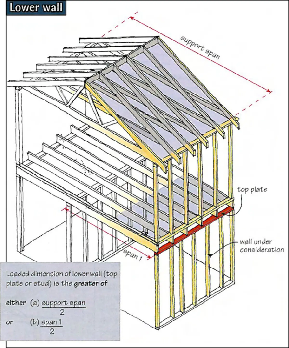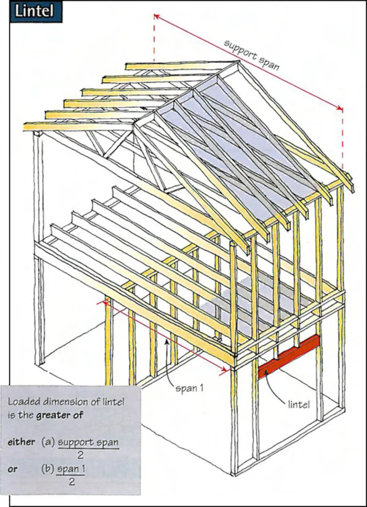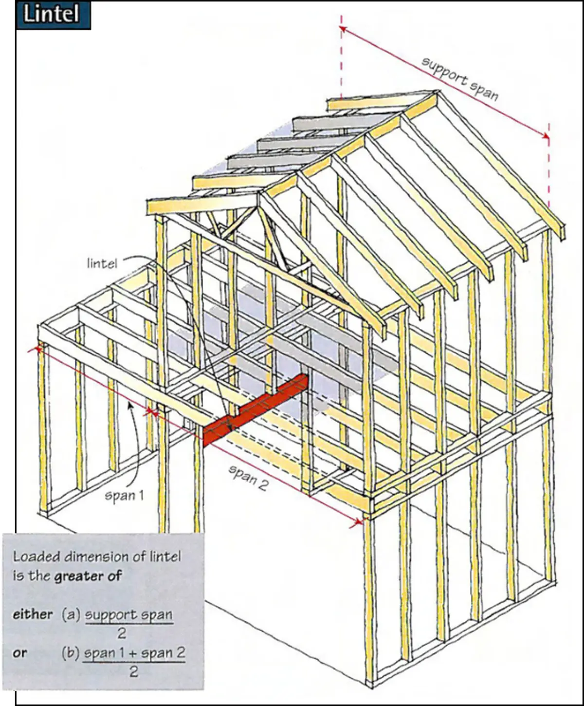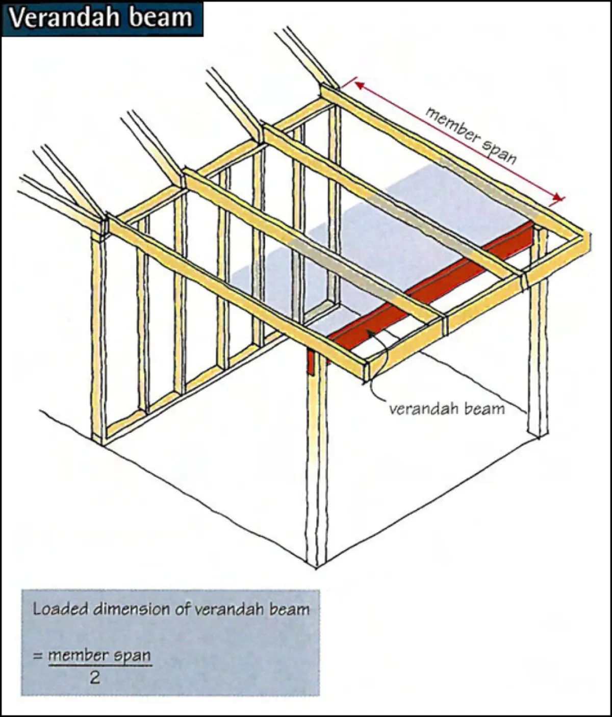


In NZS 3604:2011, loaded dimension is defined as “A measure of the weight of construction contributing to the member under construction”. How it is calculated is shown in a series of drawings in the standard.
Specifying load-bearing timbers
When we have to choose the size of a load-bearing timber member (e.g. a bearer, lintel, beam, top plate or even a wall stud), we require two vital bits of information:
1. Firstly, we need to know the member span – that is, the distance between its supports, measured along the member. Clearly, the longer the span, the deeper the timber has to be.
2. Secondly, we also need to know the load it has to support. This load is introduced to the member by the structural timbers (e,g, trusses, rafters, joists, studs) that are attached toit and at right angles to it. Clearly the longer these attached members are, the greater is the total, weight of construction that the member being selected has to support. (And this also includes the wind suction producing uplift on the member, as well as the more familiar gravity loads acting downward.) The loaded dimension calculation allows us to measure the lengths of these, and so determine the load the member has to support.
The shading in the pictures indicates the loaded area supported by the member.
Basic principle
When in doubt, consider the following basic principle:
Loaded dimension is a measure of the weight of construction that contributes load to the member under consideration.
Thinking this through as a guideline should clarify all eases that arise. However, the pictures illustrate the concept by examples.