Light timber framed buildings require two essential components to function as a complete bracing system resisting wind and earthquake forces:
- A collection of bracing elements to meet wind and earthquake demands. We should all be familiar with the NZS 3604:2011 Timber-framed buildings bracing procedure or proprietary software to do this.
- Equally important is the floor and ceiling that connects the tops of the brace walls together to transfer the applied forces into the bracing element.
Sometimes brace walls are isolated
NZS 3604:2011 provides for adequate framing and connection details at top plate level to ensure these two components act as a whole.
However, there are plenty of situations where walls with brace elements are isolated from other walls and there is no continuing top plate available for these connections. Examples are an open-plan layout, back walls of kitchens and free-standing space dividers.
In these situations, the brace wall must be connected through the ceiling framing, and there are a number of options:
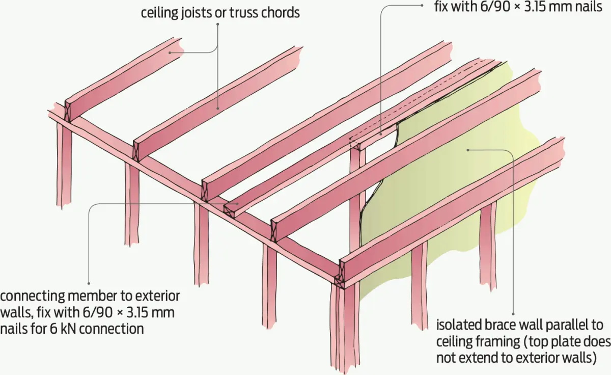
- Where the ceiling framing is parallel to the wall, a connecting member can be laid directly above the wall and connected at each end as required by NZS 3604:2011 clause 8.7.3 (see Figure 1).
- Where ceiling framing is perpendicular to the brace wall, things are a little more difficult:
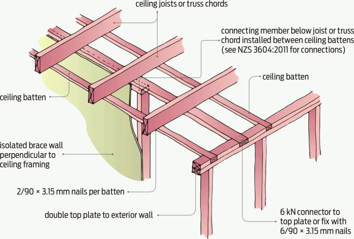
- If there is enough depth within the ceiling battens below the framing, an extra batten may be able to provide the connection (see Figure 2).
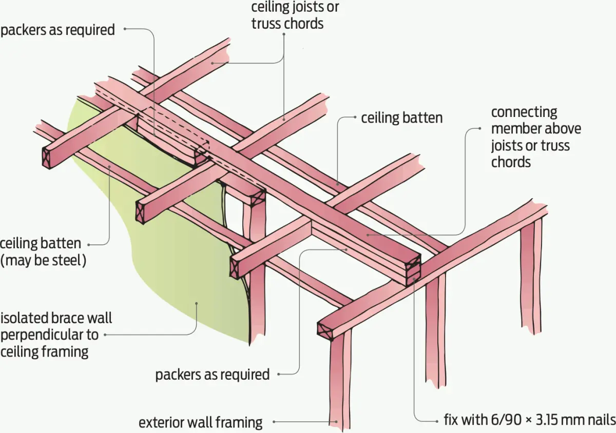
- If there are no battens or they are too shallow to fit a connecting member, it will have to be located above the framing and connected at each end using blocking or packers (see Figure 3).
These connectors will need to be fixed in place before wall or ceiling linings are installed. NZS 3604:2011 gives required connection details at each end of the connector.