

The design requirements for decks attached to a building are set out in NZS 3604:2011 Timber-framed buildings section 7.4. Where applicable, the structural and durability requirements and the selection of timber, fixings and fastenings are the same for both free-standing and attached decks.
Subfloor bracing
Subfloor bracing requirements are set out in NZS 3604:2011 section 5.
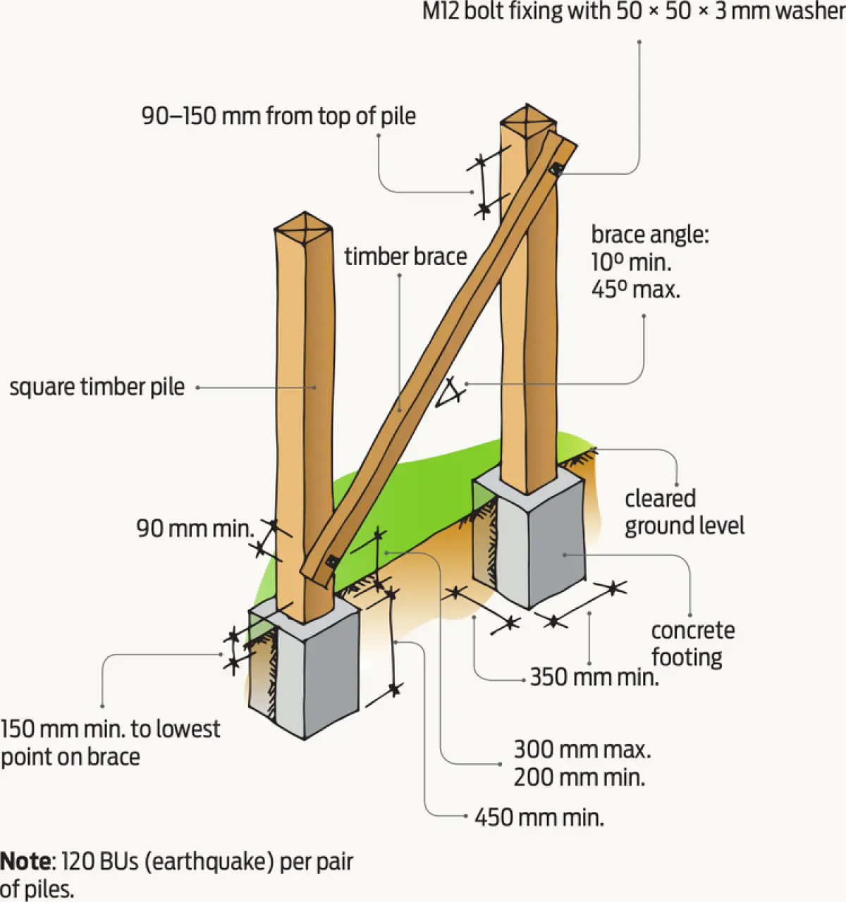
Piles may be braced, anchor or cantilevered, or a combination of these.
Calculate deck bracing demand
When determining bracing, first calculate the bracing demand for the deck.

Step 1: Select the earthquake zone from NZS 3604:2011 Figure 5.4 Earthquake zone maps.
Step 2: Obtain the bracing demand from NZS 3604:2011 Table 5.8. Using half the value for light cladding for wall, roof and subfloor and 0–25° roof pitch, this is 15 × 0.5 = 7.5 BU/m².
Step 3: Multiply the bracing demand by a multiplication factor (given at the bottom of Table 5.8) for soil class and earthquake zone.
Step 4: Multiply the resulting value by the area of the deck to calculate the total number of bracing units (BUs) required in each direction (NZS 3604:2011 5.3.1).
Example: For a proposed 10 m² (5 × 2 m) deck with an earthquake zone 3 and soil class E. From Table 5.8, the multiplication factor is 1.0, so 15 ×0.5 × 1.0 = 7.5 BU/m². Multiply 7.5 BU/m² by the area of the deck to obtain the total bracing units required gives 7.5 × 10 = 75 BUs in each direction.
Applying bracing to a deck design
There are no specific requirements in NZS 3604:2011 for bracing distribution for free-standing decks, but the following rules should be used as far as practicable. Bracing should be:
- provided in two directions at right angles to one another to provide horizontal support
- located in perimeter foundation and subfloor framing
- located in internal lines parallel to the perimeter at a maximum of 5.0 m centres
- distributed as evenly as possible along each line.
Pile height and footings
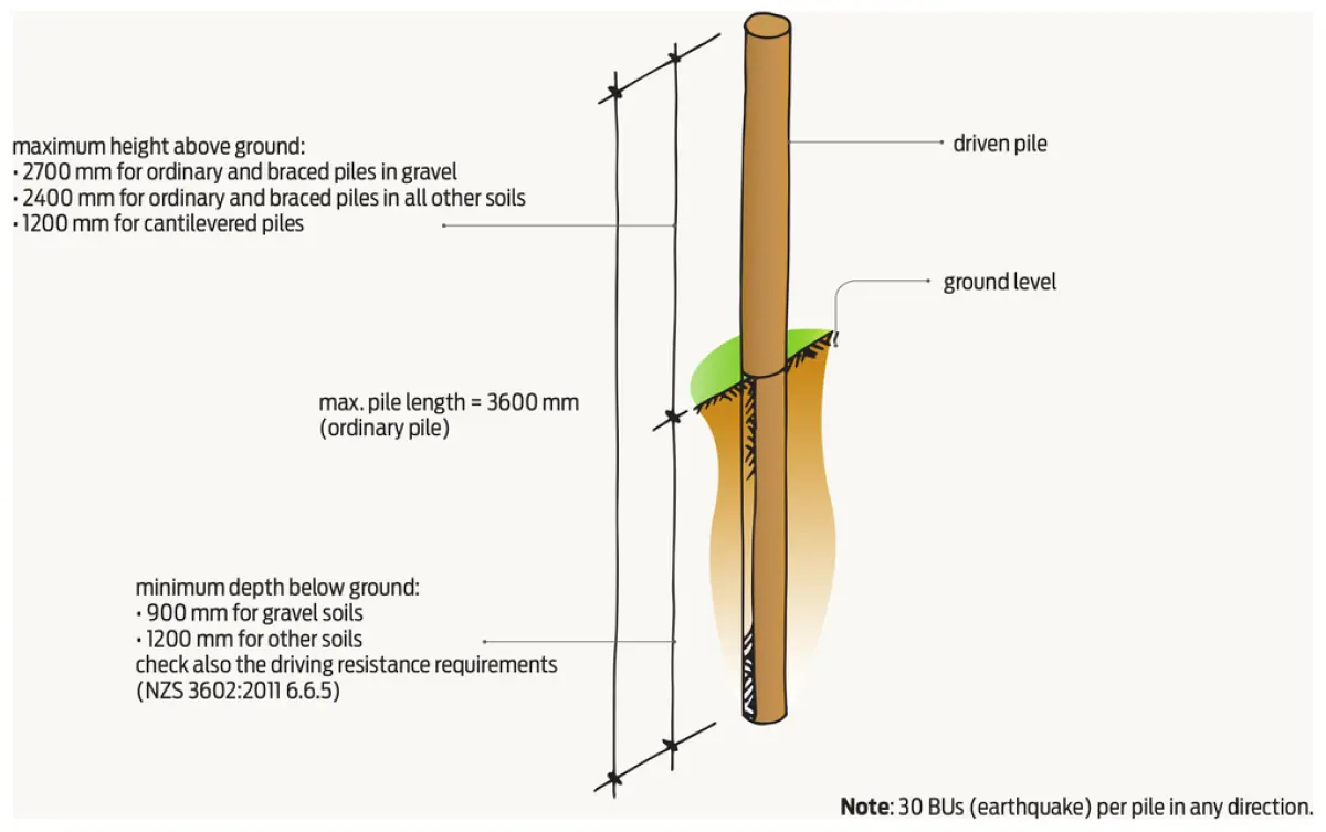
The maximum height of the piles will influence the choice of braced pile system (NZS 3604: 2011 6.4.4.1 (b)). This is summarised in Table 1 and Figures 1–5.
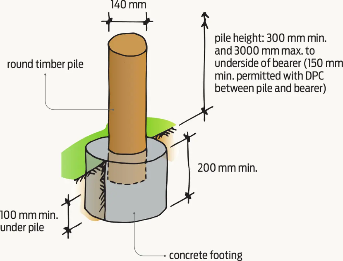
Except for driven piles, all timber piles must have a concrete footing that is at least 100 mm below the pile and be cast in situ on undisturbed good ground.
Footings below cleared ground level must have a minimum depth of:
- 200 mm for ordinary piles
- 450 mm for braced piles
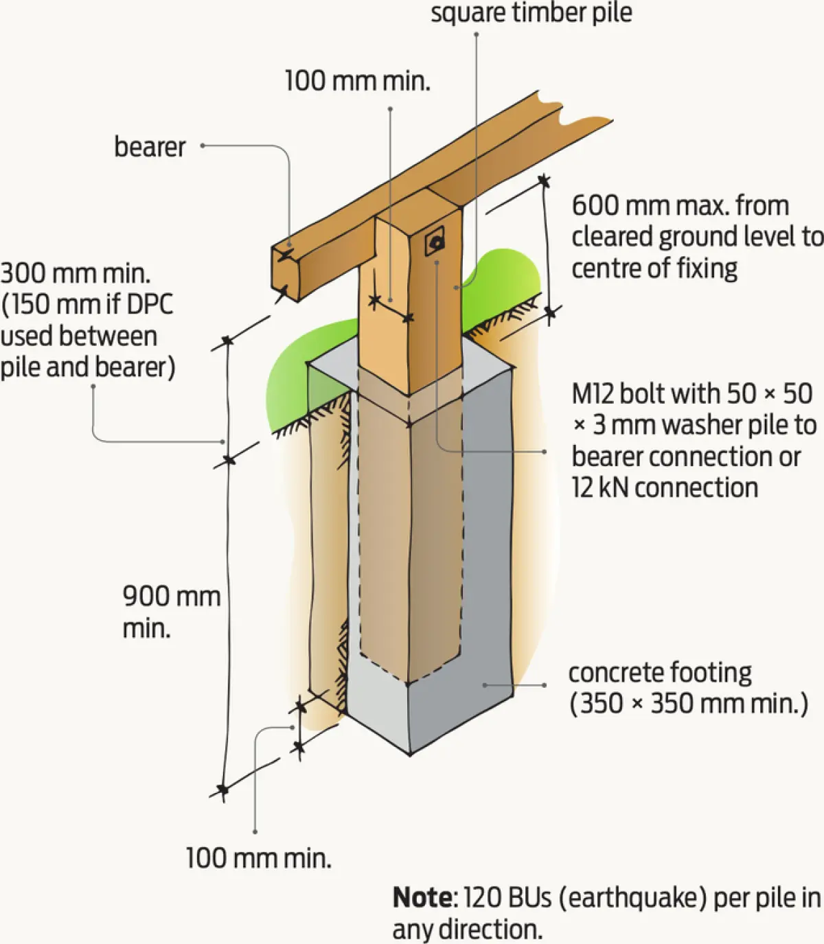
- 900 mm for anchor piles.
Maximum heights for timber piles
| TYPE OF SUBFLOOR BRACING SYSTEM | MAXIMUM PERMITTED HEIGHT ABOVE CLEARED GROUND LEVEL |
|---|---|
| Cantilevered piles | 1200 mm |
| Anchor piles | 600 mm to centre of fixing |
| Braced timber piles (when they directly support bearers) | 3000 mm |
The plan area of the footing depends on bearer and joist spans and is determined from NZS 3604:2011 Table 6.1, except that braced and anchor piles must be a minimum of 350 × 350 mm for square piles and 400 mm diameter for round piles.
Bearers
Bearer sizes are selected from NZS 3604:2011 Table 6.4 Part (b) for a 2 kPa wet-in-service floor load (NZS 3604:2011 6.12). They must:
- be continuous over two or more spans
- be laid in straight lines on edge
- have a minimum landing of 90 mm, except this may be 45 mm where butted over the support
- be jointed only over ordinary pile supports (i.e. they must not be jointed where the bearer is fixed directly to an anchor or braced pile)
- have a connection capacity at joists of:
• 12 kN minimum capacity in tension or compression along the line of the bearer, or
• 6 kN minimum capacity each on both sides of a continuous bearer.
Joists
Timber joists for decks are selected from NZS 3604:2011 Table 7.1 Part (b) for a 2 kPa wet-in-service floor load. They must be laid in straight lines on edge with top surfaces set to a common level and have 32 mm minimum bearing over supports.
Joist fixings
Joist fixings to piles or bearers are in NZS 3604: 2011 6.8.6:
- If the brace is connected to the pile and parallel to the joist direction, the two joists on either side of the brace must be fixed to the bearer with a 6 kN capacity connection in the horizontal direction.
- If the brace is connected to the joist, the joist to bearer connection must have 12 kN capacity in the vertical direction (see NZS 3604:2011 Figure 6.8).
- Bearers and joists connected to anchor piles must be fixed with:
• M12 bolts with 50 × 50 × 3 mm washers, or
• 12 mm diameter threaded rod and washers, or
• 12 kN capacity connections in tension or compression along the joist or bearer.
Trimmers and trimming joists
Where an opening (such as for stairs) is required in a deck, trimmers and trimming joists must be fitted around the opening in accordance with NZS 3604:2011 7.1.6.