


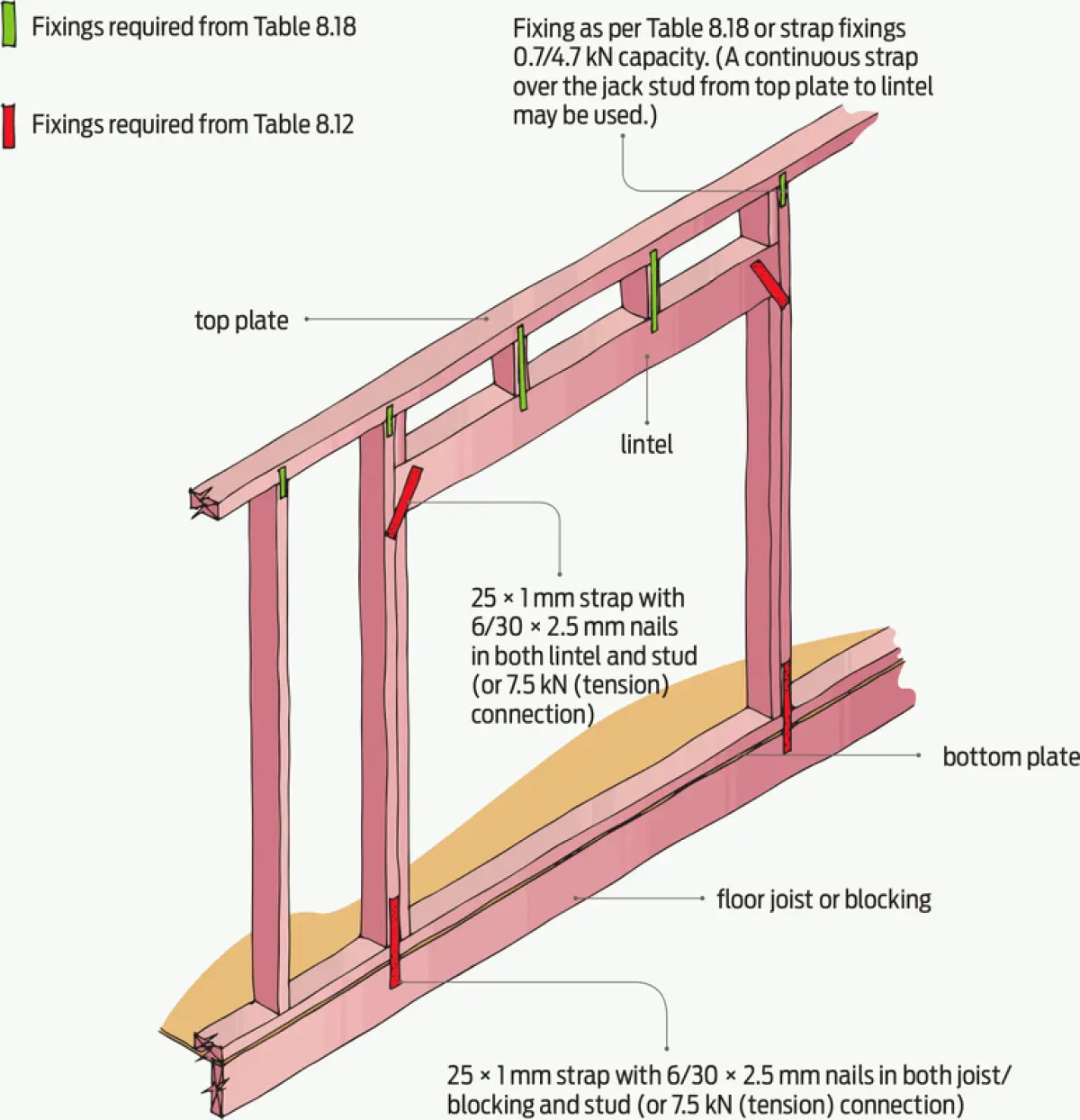
To prevent uplift, some top plates only require 0.7 kN Type A fixings attaching the top plates to studs and lintels. However, in other cases, additional securing is needed to studs and lintels (see Figure 1).
When are extra uplift fixings required?
Where lintels in NZS 3604:2011 Timber-framed buildings Figure 8.12 require uplift fixings at the ends to trimming studs, the studs and lintels will almost certainly require securing to top plates at 600 mm centres with a 4.7 kN Type B fixing (see Table 8.18).
For lintel to trimming stud requirements, see NZS 3604:2011 Figure 8.12 and Table 8.14, and Build 138 pages 33–34, Lintel fixings.
Example 1
In the first example of how to use Table 8.18, the parameters are:
- light roof
- rafters or trusses at 900 mm centres (spacing actually makes no difference to the top plate to studs and lintel fixing requirements)
- low wind zone
- loaded dimension of 4 m.
Using Table 8.18, work through the steps (see Figure 2):
- Step 1 – Choose the roof (light).
- Step 2 – Choose the wind zone and the correct roof member spacing (900 and low).
- Step 3 – Choose the loaded dimension (4 m).
- Step 4 – Align steps 2 and 3 to determine the fixing type required (Type A)
- Step 5 – Read off the fixing that is required at 600 centres maximum.
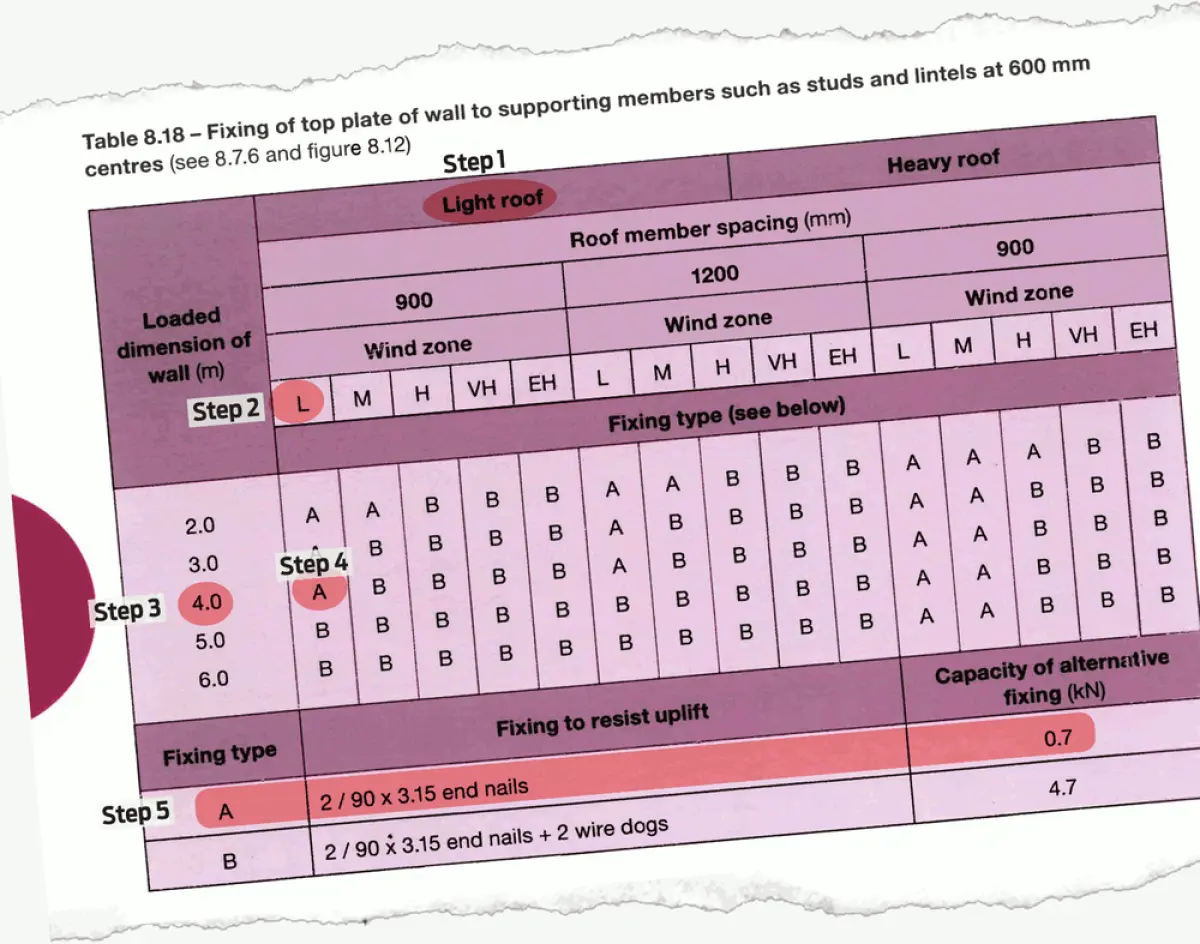
For this example, 2/90 × 3.15 mm end nails or an alternative fixing that provides 0.7 kN in tension are required. It is likely the nails will be used.
Example 2
With our second example, we have:
- heavy roof
- rafters or trusses at 900 mm centres
- high wind zone
- loaded dimension of 4 m.
Using Table 8.18, work through the steps again (see Figure 3):
- Step 1 – Choose the roof (heavy).
- Step 2 – Choose the wind zone (high).
- Step 3 – Choose the loaded dimension (4 m).
- Step 4 – Align steps 2 and 3 to determine the fixing type required (Type B).
- Step 5 – Read off the fixing that is required at 600 centres maximum.
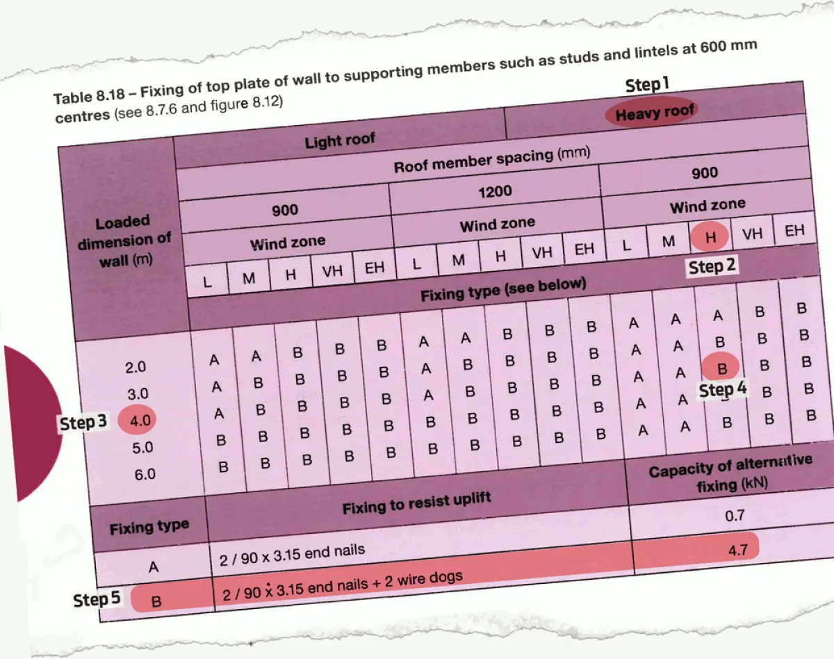
For this example, the fixings required are 2/90 × 3.15 mm end nails plus 2 wire dogs or an alternative fixing that provides 4.7 kN in tension, commonly a strap.
Continuous strap for jack studs
Table 8.18 requires fixings to attach the top plate to the studs and to the lintels at 600 mm centres. It is common to have jack studs above lintels, so the fixing will be required for both where:
- the jack stud attaches to the top plate
- the jack stud attaches to the top of the lintel.
It is usually easier to use the alternative fixing of a strap running continuously from top plate to the lintel where jack studs are short.
Alternative 4.7 kN fixing
Table 2.2 in NZS 3604:2011 has a reference guide to fixing types and their locations.
Type A and B fixings in Table 8.18 are in tension, as is Type E in Table 2.2:
- Type A = 0.7 kN or 2/90 × 3.15 mm end nails
- Type B = 4.7 kN or 2/90 × 3.15 mm end nails + 2 wire dogs
- Type E = 4.7 kN or 2/90 × 3.15 mm skew nails + 2 wire dogs
Comparing Type B and E fixings, both have 2 wire dogs but one has 2 end nails and the other has 2 skew nails giving the same rating in tension.
Alternative 0.7 kN fixing into jack studs
Obviously, it is not possible to use end nails through a lintel into a jack stud.
From the above, it seems reasonable to assume that, where wire dogs were not necessary (Type A fixing), 2 skew nails through a jack stud into the top of the lintel would give the 0.7 kN.
Double top plate
Where a double top plate is required, the fixing capacity should be continuous through the plates.
Bottom plate
As a final note, on a slab floor, Figure 8.12 requires bolts through the bottom plate within 150 mm of the trimming stud.