

Understanding all the building components requirements and especially the correct sequence of installation is crucial to ensuring weathertight performance.
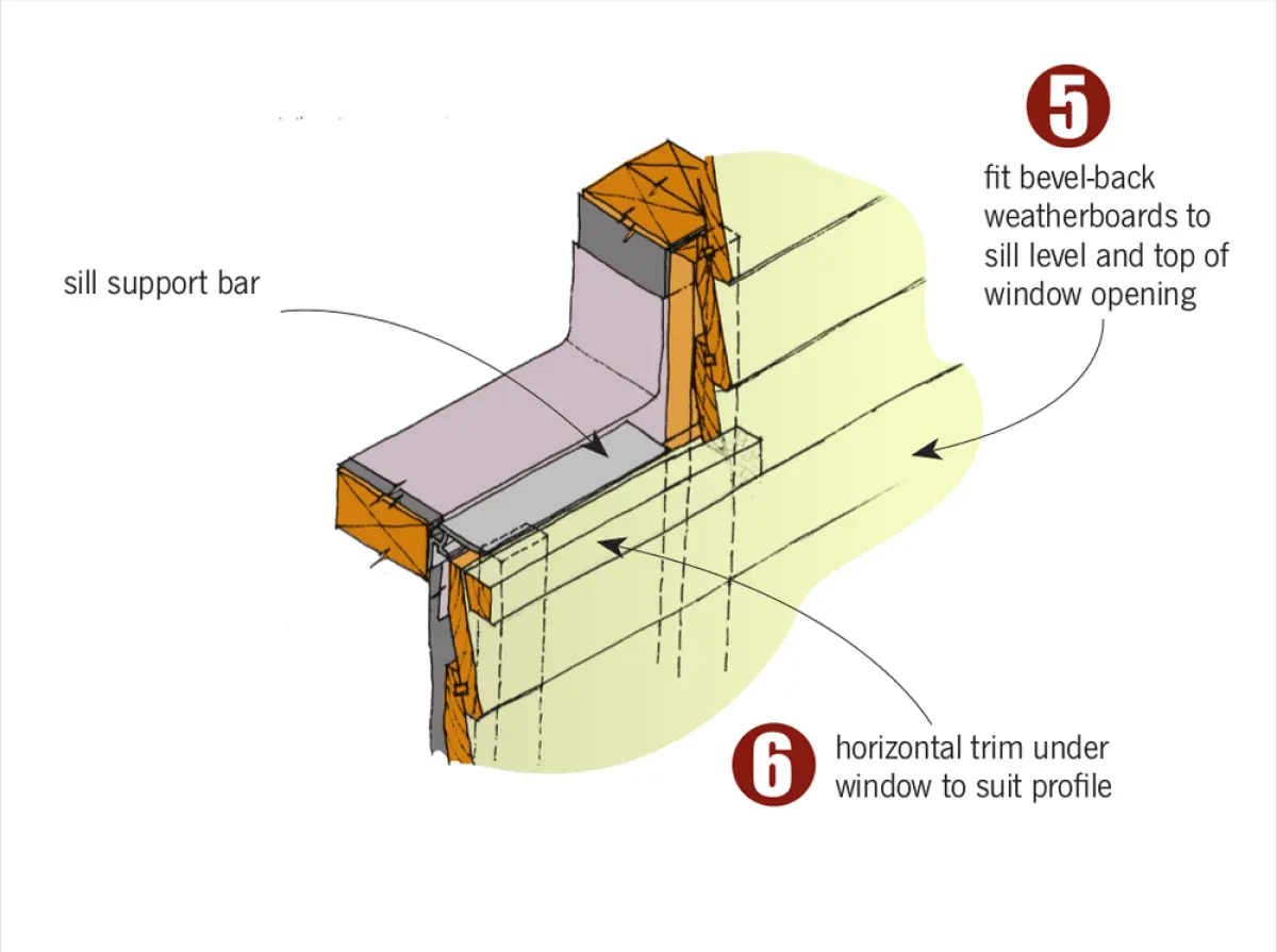
Sill support bar
Window installation in cavity walls requires the fitting of a sill support bar to all doors and windows over 600 mm wide (E2/AS1 9.1.10.4).
The sill support bar must allow any water that gets past the external cladding to drain away, and it must maintain at least 1,000 mm² clear opening per metre length of window between the drainage cavity and the window or door trim cavity to allow air passage. To do this, sill support bars incorporate drainage and ventilation openings.
Sill support bars must end within 100 mm of the trimming stud.
Sill support bars must also comply with BRANZ Evaluation Method EM6, Verification Method E2/VM1 and Acceptable Solution B2/AS1.
Additionally, manufacturers must provide information about the support bar loading limits.
Jamb flange gap
For fibre-cement sheet or ply claddings, E2/AS1 requires a 5 mm gap for sealant to be left between the jamb flange and cladding.
Other key requirements for cavity construction
Other points to bear in mind:
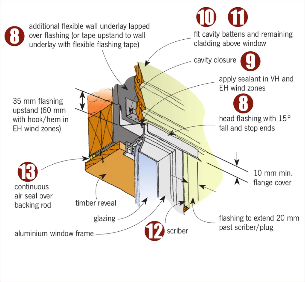
- In extra high (EH) wind zone situations, flashing upstand dimensions must be 25 mm more than the dimensions stated in E2/AS1 section 4.4.3 or Table 4.5.1.1, and all flashings must have a hook or a hem.
- In very high (VH) and extra high (EH) wind zones, sealant must be inserted between the head flashing and the window head flange as shown in E2/AS1 Figure 9.1.10.1.
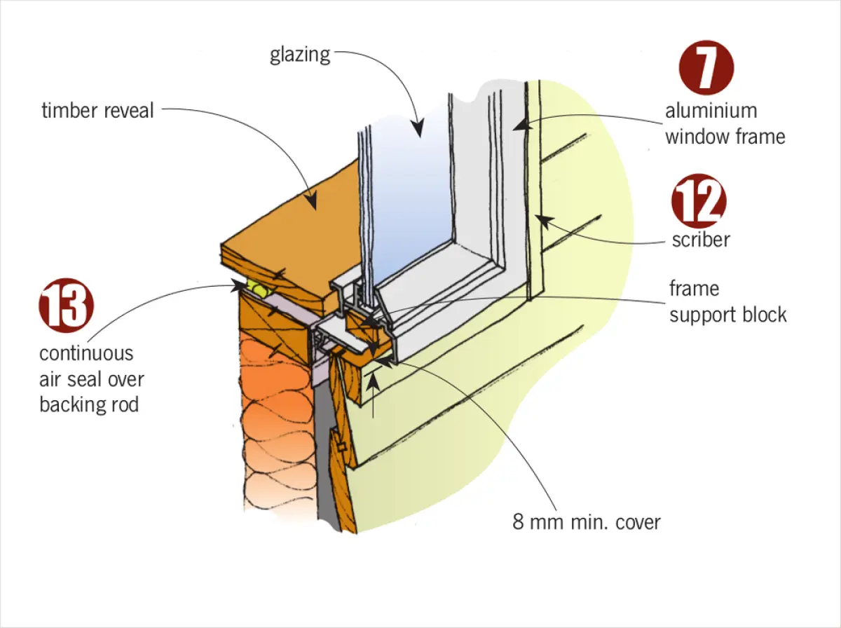
- The minimum cover to the cladding for window sill flanges is 8 mm, while the minimum jamb flange cover is 10 mm (Table 4.5.1.1).
- Factory-fitted soakers are required behind the sill/jamb mitred frame joints of aluminium windows and doors.
SEQUENCE TO INSTALL A WINDOW INTO CLADDING WITH CAVITY
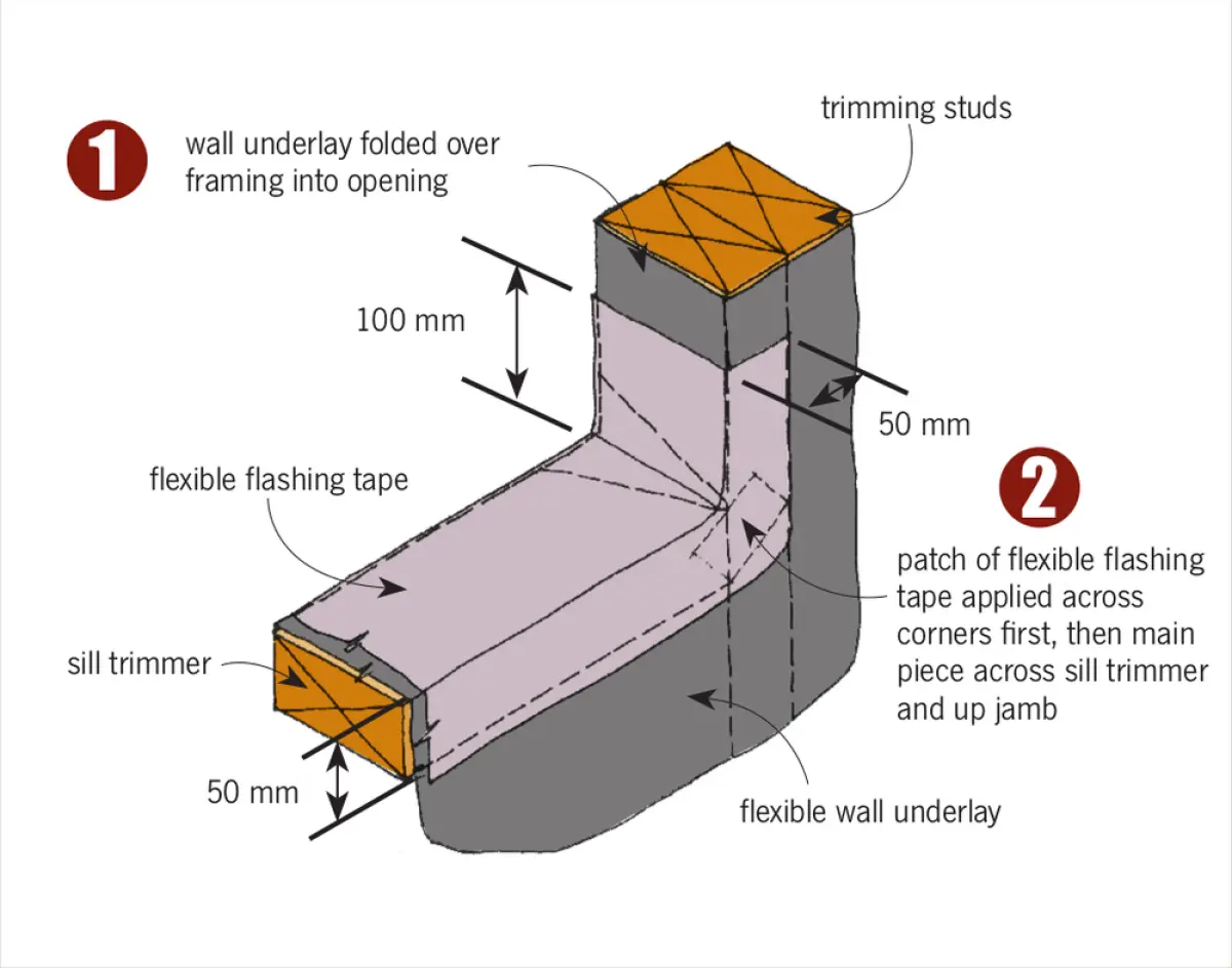
STEP 1 Install flexible wall underlay across the full window opening. Make diagonal cuts, then fold the underlay round the opening and secure. For rigid underlay, trim to opening.
STEP 2 Install a small patch of flexible flashing tape across corners. Then install flexible flashing tape in the corners and:
- at the top corners 100 mm along the head and down the jamb and turned out 50 mm over the face of the wall
- across the sill trimmer with 100 mm return up the jambs and turned out 50 mm over the face of the wall.
If rigid underlay is used, tape the whole opening.
STEP 3 Install the sill support bar.
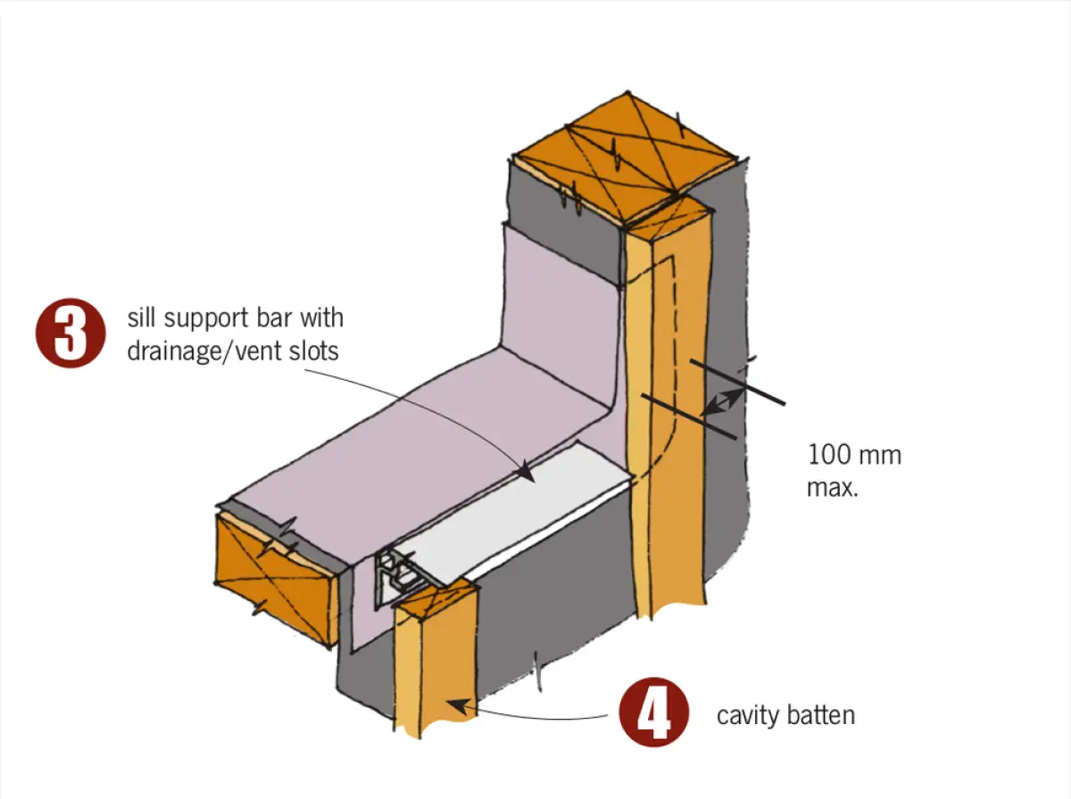
STEP 4 Fix cavity battens beside and below the window opening.
STEP 5 Fix cladding over cavity battens below window and to side of opening.
STEP 6 Fix horizontal trim under window to suit profile. Notch edge over cladding as required.
STEP 7 Install windows to meet the minimum flange cover – 8 mm at sill, 10 mm at jamb. No gap is required at jambs or sills unless fibre-cement sheet or ply cladding.
STEP 8 Fit head flashing and cover with either additional wall underlay extended up to next lap or flashing tape for full length of the flashing. Apply sealant between head flashing and window head flange in very high (VH) and extra high (EH) wind zones before fitting flashing. Ensure head flashing is stop-ended.
STEP 9 Fit cavity closure.
STEP 10 Fit cavity battens above window opening.
STEP 11 Fix the remaining cladding above the opening.
STEP 12 Install scribers and plugs to suit weatherboard profile.
STEP 13 Install air seal over backing rod around perimeter of the trim opening shortly before fixing interior linings.