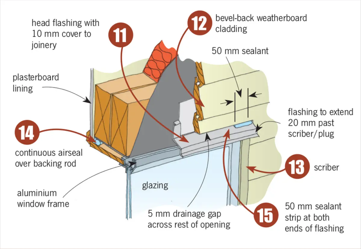


Direct-fix claddings have requirements and restrictions in E2/AS1 that are different to claddings on a cavity. With openings in walls especially, designers should understand the requirements in a few key areas:
- the sill tray flashing design
- installation of jamb battens
- head flashing sealant at each end of the window.
Sill tray flashing
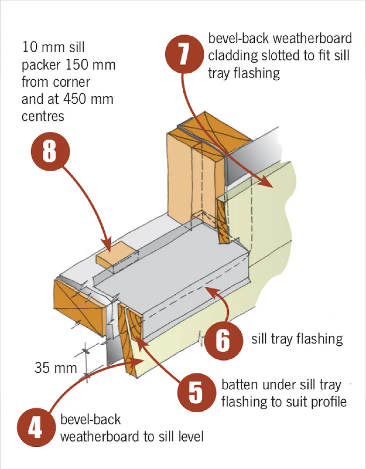
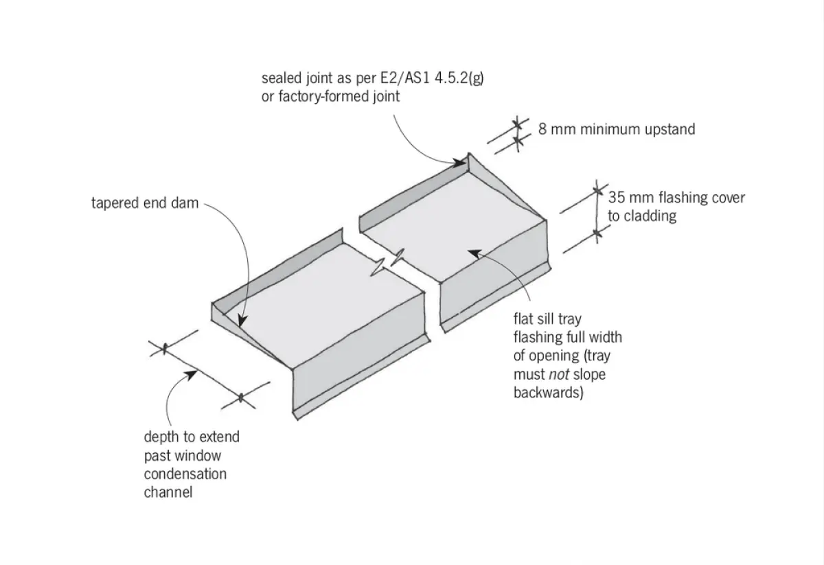
Windows installed in openings with direct-fix wall claddings must have a sill tray flashing as shown in Figure 1. It must:
- extend for the full width of the opening between trimming studs
- have an 8 mm back upstand
- have tapered end upstands
- provide 35 mm minimum cover to the cladding.
The sill tray can be flat.
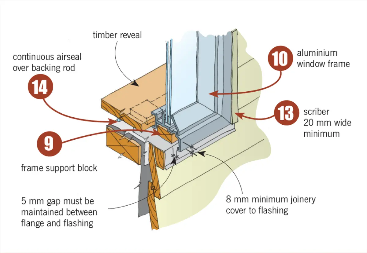
The window must be supported on frame support blocks (supplied by the joinery manufacturer) and have a minimum 8 mm flange cover over the sill tray flashing downturn with a 5 mm unsealed air gap.
The jamb flanges must have a 10 mm minimum cover, and if not protected by a scriber or plug, the gap must be sealed. The packers underneath the timber reveal to the sill need to be a minimum of 8 mm – measure with the flashing in place to get the correct height.
Jamb battens
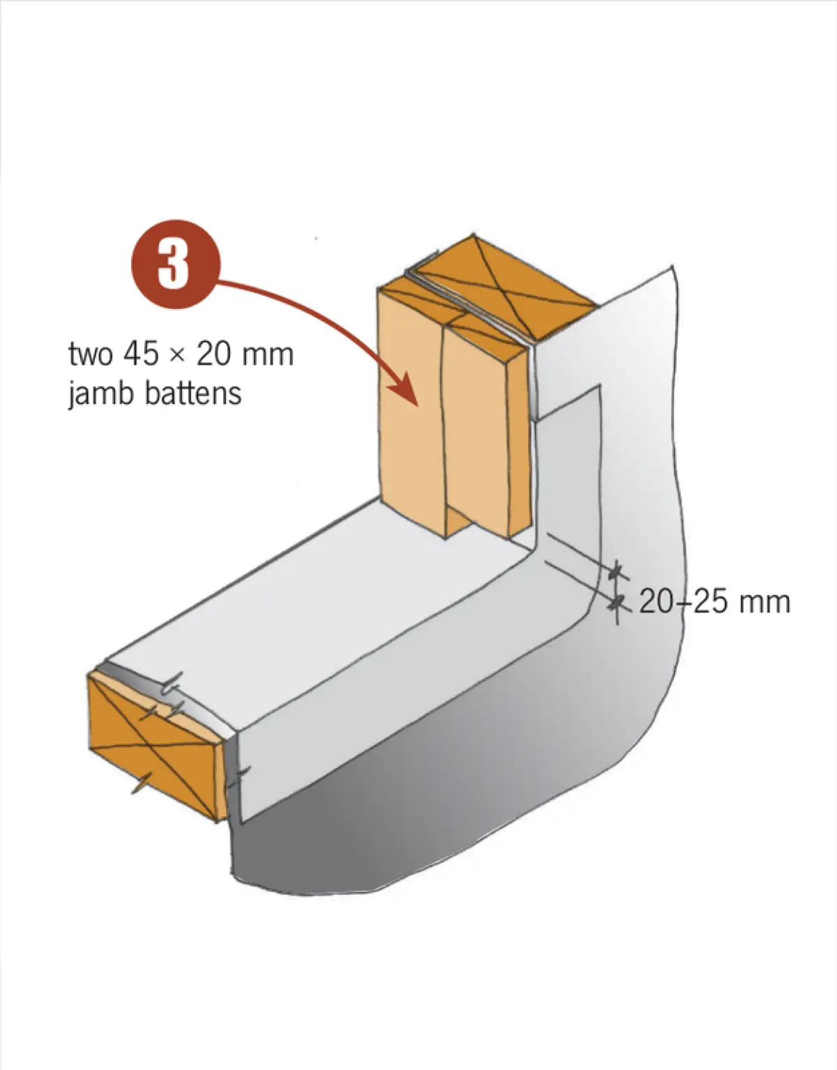
Window openings with direct-fix wall claddings require two 45 × 20 mm vertical jamb battens to be fixed to the face of the trimming stud on each side of the opening:
- The inside batten must be fitted between the lintel and the sill trimmer.
- The outside batten is fitted to the underside of the lintel but is stopped 20–40 mm short of the sill trimmer. This allows the sill flashing to extend along the full length of the sill trimmer between trimming studs without requiring stud notching.
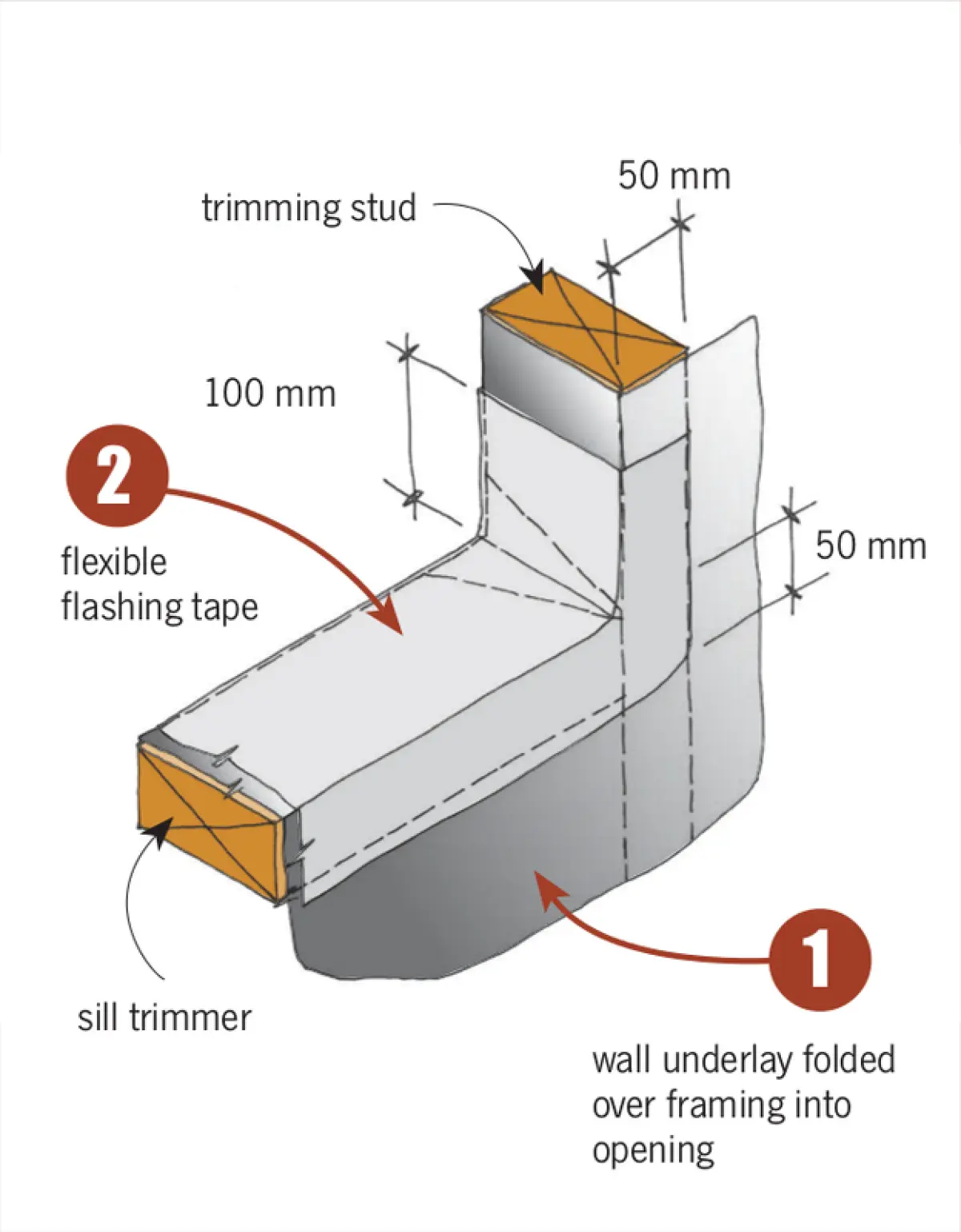
The battens are installed after the timber-framed opening has been protected by folding the wall underlay back around the frame opening, then covering the corners and the full length of the sill trimmer with flexible flashing tape.
The cladding is fixed and trimmed to the battens, not the studs. The window opening width should be measured after the sill battens and the sill tray have been installed.
Head flashing sealant
A 50 mm long bead of sealant must be installed between the cladding and each end of the head flashing to prevent water tracking around the end of the flashing.
SEQUENCE TO INSTALL A WINDOW WITH DIRECT-FIX CLADDING
Step 1 – Install wall underlay across the full window opening. Make diagonal cuts, then fold the underlay round the opening and secure.
Step 2 – Install flexible flashing tape in the corners and across sill trimmer:
- 100 mm along the head and down the jamb at the top corners and turned out 50 mm over the face of the wall
- across the full length of the sill trimmer and 100 mm up jambs at bottom corners and turned out 50 mm over the face of the wall.
Step 3 – Install jamb battens to both trimming studs.
Step 4 – Fix cladding up to sill level.
Step 5 – Fix horizontal trim batten (which will be under the sill tray flashing).
Step 6 – Fit the sill tray flashing. Provide a 35 mm minimum cover over the cladding.
Step 7 – Fix the cladding up to the top of the opening. Cut slots in the cladding as required round the sill tray flashing.
Step 8 – Install sill packers behind the sill flashing to support timber window reveal.
Step 9 – Install the window frame support blocks (supplied with window by manufacturer).
Step 10 – Install the window providing the requisite minimum flange cover, i.e. 8 mm at the sill, 10 mm at the jambs. Ensure that a minimum 5 mm gap between the window flange and sill tray flashing is maintained.
Step 11 – Fit head flashing and cover either with additional wall underlay extended up under next lap or flashing tape for the flashing full length.
Step 12 – Fix the remaining cladding.
Step 13 – Install scribers or plugs to suit weatherboard profile. Scribers need to be 20 mm wide minimum to cover sill flashing.
Step 14 – Install airseal over PEF backing rod around perimeter of the trim opening.
Step 15 – Install a 50 mm bead of sealant between the cladding and head flashing at each end of the window.