

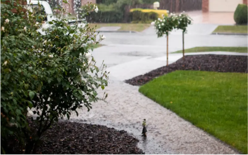


The Ministry for the Environment says there is evidence that climate change is increasing the frequency and severity of events such as heavy rainfall. Given that homes designed today will have to cope with extreme weather events for many decades, it is important to make sure that gutters are designed to cope.
Designers must determine:
- rainfall intensity for the location
- catchment area of the gutter
- cross-section
- fall
- outlet and downpipe type and size
- overflows.
Rainfall intensity
For sizing gutters, rainfall intensity must be determined for the location. For external gutters this is a measurement in mm/hour of the rainfall for a storm with a 10% probability of occurring annually and with a 10-minute duration. Rainfall intensity in different areas can be found in E1/AS1 Appendix A or in E1/AS2 (which cites AS/NZS 3500.3:2021 Plumbing and drainage Part 3: Stormwater drainage.) Appendix E of AS/NZS 3500.3:2021 has a table of rainfall intensities around New Zealand for 10% and 2% probabilities of occurring annually.
E1/AS1 allows for a minimum rainfall intensity of 100 mm/hour when sizing an external gutter, but always check the data for a specific location – a higher figure needs to be used for quite a few locations.
You can also use NIWA’s High Intensity Rainfall Design System (HIRDS) available at niwa.co.nz/information-services/hirds.
The 10% probability approach used in E1/AS1 and E1/AS2 comes from the first performance requirement in E1 that ‘surface water, resulting from an event having a 10% probability of occurring annually and which is collected or concentrated by buildings or sitework, shall be disposed of in a way that avoids the likelihood of damage or nuisance to other property’.
The New Zealand Metal Roofing Manufacturers Association Code of Practice v3.0 (CoP) takes a more conservative approach, using figures for a 50-year average return interval, which are higher than the 10-year figures. It bases this on the second performance requirement in E1: ‘Surface water, resulting from an event having a 2% probability of occurring annually, shall not enter buildings.’
E1/AS2 requires 50-year figures to be used for internal and valley gutters.
Gutter catchment
Catchment can be calculated using the Acceptable Solutions or the CoP. E1/AS1 Figure 15 uses the plan area of the roof discharging to a section of gutter. BRANZ recommends that the actual roof plane area (the sloping surface) is used when calculating gutter and downpipe sizes, not the plan area. The calculations in the CoP are based on the plane area.
Walls discharging into a roof should also be considered. They are not considered in E1/AS1 but are in E1/AS2 and the CoP.
Cross-section area
The Acceptable Solutions and the CoP allow designers to work out minimum cross-sectional area of each section of external gutter. This can be increased for higher rainfall intensity where required. The minimum required cross-section of any gutter in E1/AS1 5.1.4 is 4,000 mm².
Internal brackets in a gutter can increase the risk of leaves, twigs and other debris collecting – external brackets allow a smoother flow of water.
Fall in external gutters
The angle of fall in external gutters is crucial in avoiding overflows:
- The CoP 5.4.2.1 says: ‘All gutters must have a minimum fall of 1:500 (2 mm in 1 m), the COP recommends 1:200 (5 mm in 1 m), as it will improve drainage and self-cleaning.’
- Manufacturers of metal eaves gutterstypically specify a minimum 1:500 (2 mm in 1 metre).
- A major producer of uPVC spouting says: ‘Ensure a min fall of 5 mm for every 10 m of run’ (1:2000).
- E1/AS1 5.3.1 gives no minimum falls forexternal gutters and refers to E2/AS1 for the design of valley gutters.
The conservative approach is the CoP recommendation of an external gutter fall of 1:200 (5 mm in 1 m). This may require additional downpipes to accommodate the fall within the fascia width and to minimise the visual effect of the fall.
Outlet and downpipe type and capacity
Outlet and downpipe requirements are covered in the Acceptable Solutions, and there is a downpipe capacity calculator in the CoP.
In higher catchment areas, stormwater should go into a rainhead to increase the head of water entering a downpipe and provide an overflow mechanism.
Where a downpipe from a higher roof discharges to a roof below, the outlet should have a spreader to prevent a concentrated water flow (Figure 20 in E2/AS1). The lower roof gutter and downpipe design should take account of the flow from both roofs, with an increased overflow provision.
Siphonic outlets exclude air from a downpipe, giving greater capacity and flow rates than a gravity system where pipes carry air and water. Generally installed in commercial buildings, siphonic outlets may be appropriate for some residential buildings and locations.
Overflows
Overflows are not required in external gutters in E1/AS1, but BRANZ recommends them. Overflow outlets should discharge outside the building, away from windows and doors but in a visible location so the building occupier can readily see that maintenance or repair is required. AS/NZS 3500.3 gives examples of overflow measures for eaves gutters in an appendix.
Valley gutters
Valley gutters that deliver water to an external gutter can be made deeper to accommodate larger flows. Where possible, a drainage outlet or downpipe should be installed close to the exit location of the valley.
Internal gutters
If an internal gutter – sometimes called a box gutter – overflows, water can enter the building. The best approach is to avoid internal gutters altogether.
There are specific requirements for internal gutters in E1/AS1 and E2/AS1. You can take a conservative approach by designing:
- for a rainfall intensity not less than 200mm/hour – rather than 100 mm/hour
- wider gutters (>300 mm) for easymaintenance access
- a 1:60 fall for better drainage – greaterthan the 1:100 required in E2/AS1
- gutter sides that extend well above outlet level
- enough freeboard to prevent overflow in windy conditions
- outlets at 12 m maximum intervals, givinga maximum gutter run of 6 m if regularly spaced
- overflows at locations where overflowwill quickly be noticed.
The CoP provides an alternative method of calculating internal gutter sizes that incorporates many factors.
Key points
- E1/AS2 and the CoP especially take a moreconservative approach than E1/AS1.
- When calculating roof catchments,use the roof plane area and not thehorizontal plan area.
- The CoP recommends a conservativeexternal gutter fall of 1:200 (5 mm in 1 m).
- Overflows are not a requirement inexternal gutters in E1/AS1 but arerecommended.
- Internal gutters should be avoidedwherever possible.