

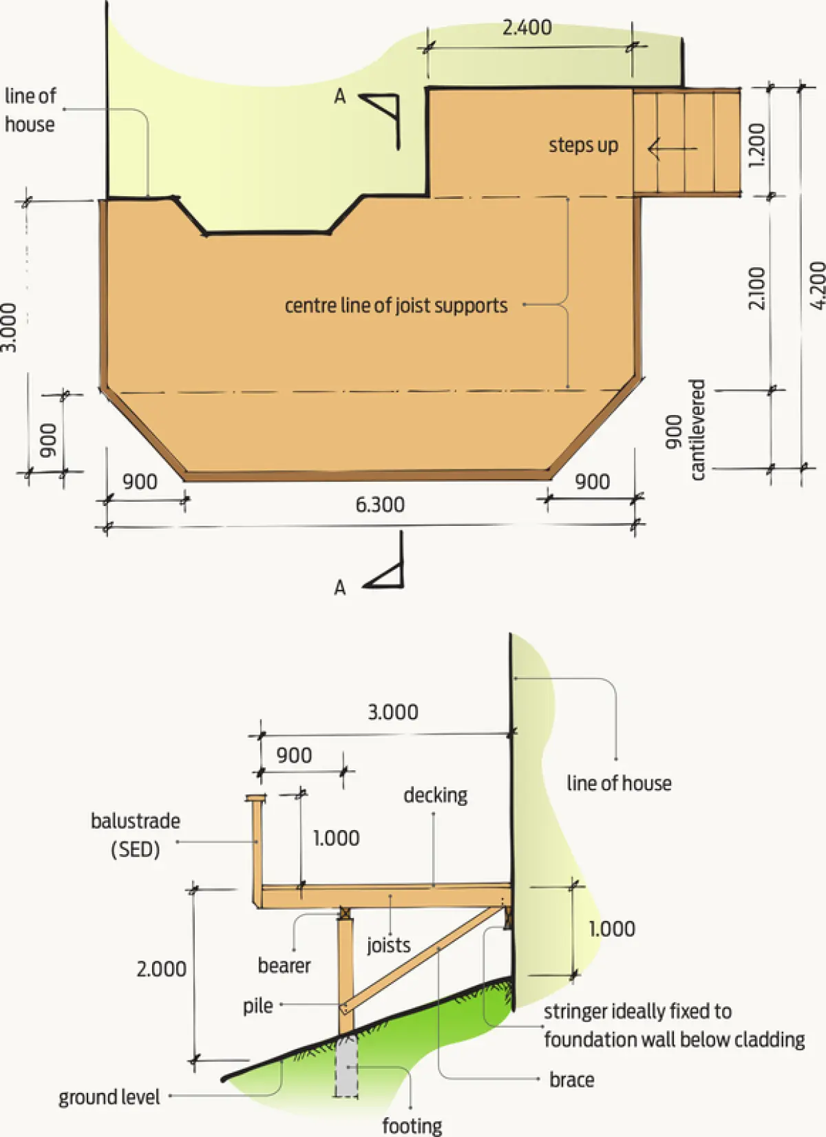
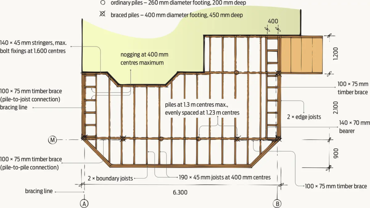
An L-shaped deck addition is proposed for an existing house. It will be 6.3 m long in one direction, project 3.0 m from the face of building and have a total area of 21 m² (see Figure 1). The finished deck level will be 100 mm below the floor level of the house.
Getting started
The requirements of foundations, subfloor framing, bracing, decking selection, fastenings and fixings are in NZS 3604 section 7.4.
The house is in earthquake zone 3 (NZS 3604 Figure 5.4), and as there is no subsoil classification, E must be assumed and a multiplication factor of 1.0 (NZS 3604 clause 5.3.3 and Table 5.8) used for bracing calculations.
The section slopes away from the house, starting at approximately 1.0 m below floor level adjacent to the house to approximately 2.0 m below floor level at the edge of the deck. Joists are to be cantilevered 900 mm beyond the line of the piles and bearer (see Figure 1).
The building owner would like to use a 32 mm kwila decking, so joist spacings may be up to 600 mm. However, as the deck is to support a cantilevered balustrade, NZS 3604 clause 7.4.1.3 requires that joists must be at 400 centres maximum and they at least 190 mm deep.
Step 1: Select the timber
New Zealand Building Code clause B2 Durability sets out the durability requirements for building elements and cites NZS 3602:2003 Timber and wood-based products for use in building for timber treatment levels.
Generally, structural elements must have not less than 50-year durability, and stairs, stair handrails and decking require not less than 15-year durability. All structural fixings must have the same durability as the elements with which they are associated and will need to be stainless steel.
So, from NZS 3602: Table 1:
- piles must be H5 treated (ground contact)
- all other structural members, i.e. bearers, stringer, braces, joists and safety barrier support posts, must be at least H3.2 treated (exposed to the exterior but not in ground contact).
NZS 3604 clause 2.3.2 requires SG8 (structural grade) timber for wet-in-service conditions.
Step 2: Calculate the bracing requirement
Using the multiplication factor E for zone 3 = 1.0
15 BU/m² × 1.0 = 15 BU/m²
Paragraph 7.4.2.2 states that decks that project more than 2.0 m from the building require subfloor bracing at half the bracing demand required by Table 5.8 for ‘light/light/light’ cladding, 0° roof pitch and for ‘subfloor structures’. So, divide the number of BUs required by two:
15 BU/m² / 2 = 7.5 BU/m² are required.
Multiply the number of BU/m2 by the area of the deck to obtain the total BUs required for the deck:
7.5 BU/m² × 21 m² = 157.5 BUs in each direction.
Bracing may be provided by anchor, braced and cantilevered piles. NZS 3604 section 6 Brace pile gives the bracing capacity ratings of subfloor bracing elements. Both anchor and braced piles provide 120 BUs per bracing element.
However, as anchor piles may only be 600 mm above ground level and the ground level is 1.0–2.0 m below the deck, anchor piles cannot be used.
Similarly, cantilevered piles may only extend 1.2 m maximum above ground level and in addition provide only 30 BUs per pile, requiring more cantilevered piles to achieve the BUs needed.
So braced pile systems provide the best solution. As they provide 120 BUs for earthquake resistance, two braced pile systems are required in each direction.
Braces will be less than 3.0 m long, so the brace size may be 100 × 75 mm.
Step 3: Selecting joists
As the line of support (i.e. piles and bearer) is 2.1 m from the house, according to NZS 3604 Table 7.1(b) (2 kPa floor load and wet in service), 140 × 45 mm joists may be used, and Table 7.2 for cantilevered joists allows a cantilever of up to 1150 mm.
However, at the bottom of Table 7.2, a note states that 140 mm joist depth is insufficient where cantilevered balustrades are to be used (as in this situation). So select the next size up, 190 × 45 mm joists. At 400 centres, these may cantilever up to 1600 mm.
Step 4: Selecting bearers
Select bearers from NZS 3604 Table 6.4(b) (2 kPa floor load and wet in service). To determine the loaded dimension of the bearers, refer to NZS 3604 Definitions.
From Figure 1.3(G), the loaded dimension = (span 1/2) + span 2 (where span 1 = 2.1 m and span 2 = 900 mm) = 2.1/2 + 900 = 1.95 m
From NZS 3604 Table 6.4(b) (2 kPa floor load and wet in service):
- for maximum bearer span = 1.3 and a loaded dimension of 2.3 m, bearer = 140 × 70 mm, or
- for maximum bearer span = 1.65 and loaded dimension 2.7 m, bearer = 190 × 70 mm.
Use 140 × 70 mm bearers with supports at 1.3 m centres maximum.
Step 5: Selecting stringers
Stringers will be used against the house. Ideally, stringers should be packed off and fixed to the foundation wall. Maximum joist span is 2.1 m, so from NZS 3604 Table 6.5, the stringer may be either:
- 140 × 45 mm
- 190 × 45 mm.
Both will need bolt fixings at 1600 mm centres.
Step 6: Selecting piles and footings
A combination of ordinary and braced piles must be used. Select 140 mm diameter timber piles.
For pile footings, use NZS 3604 Table 6.1.
For ordinary piles:
- maximum bearer span = 1.3 m; maximum joist span = 2.1 m
- footings – 260 mm diameter, 200 mm minimum deep (NZS 3604 Figure 6.2).
For braced piles:
- two systems in each direction
- footings – 400 mm diameter, 450 mm minimum deep (NZS 3604 clause 6.8.1.1).
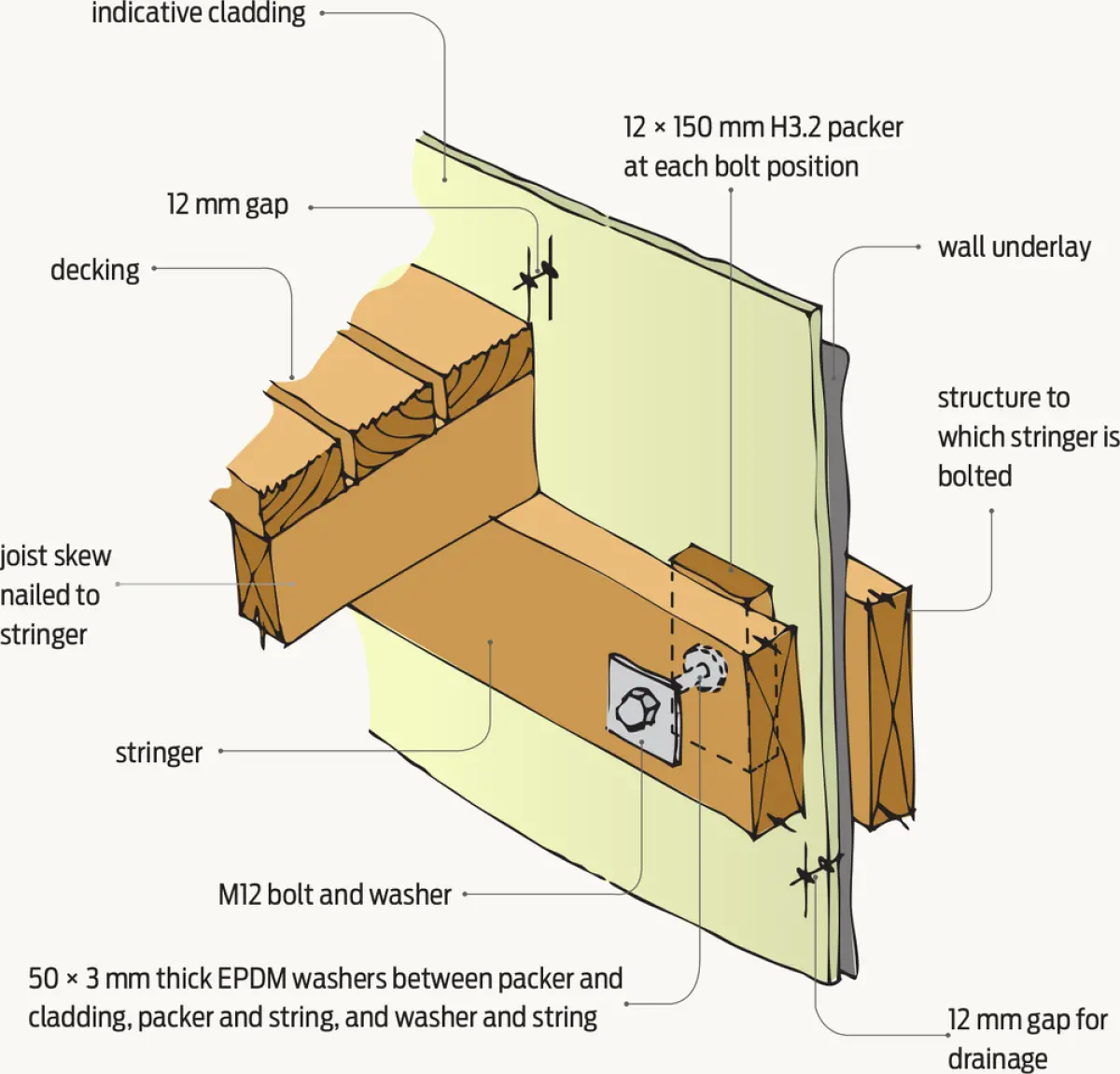
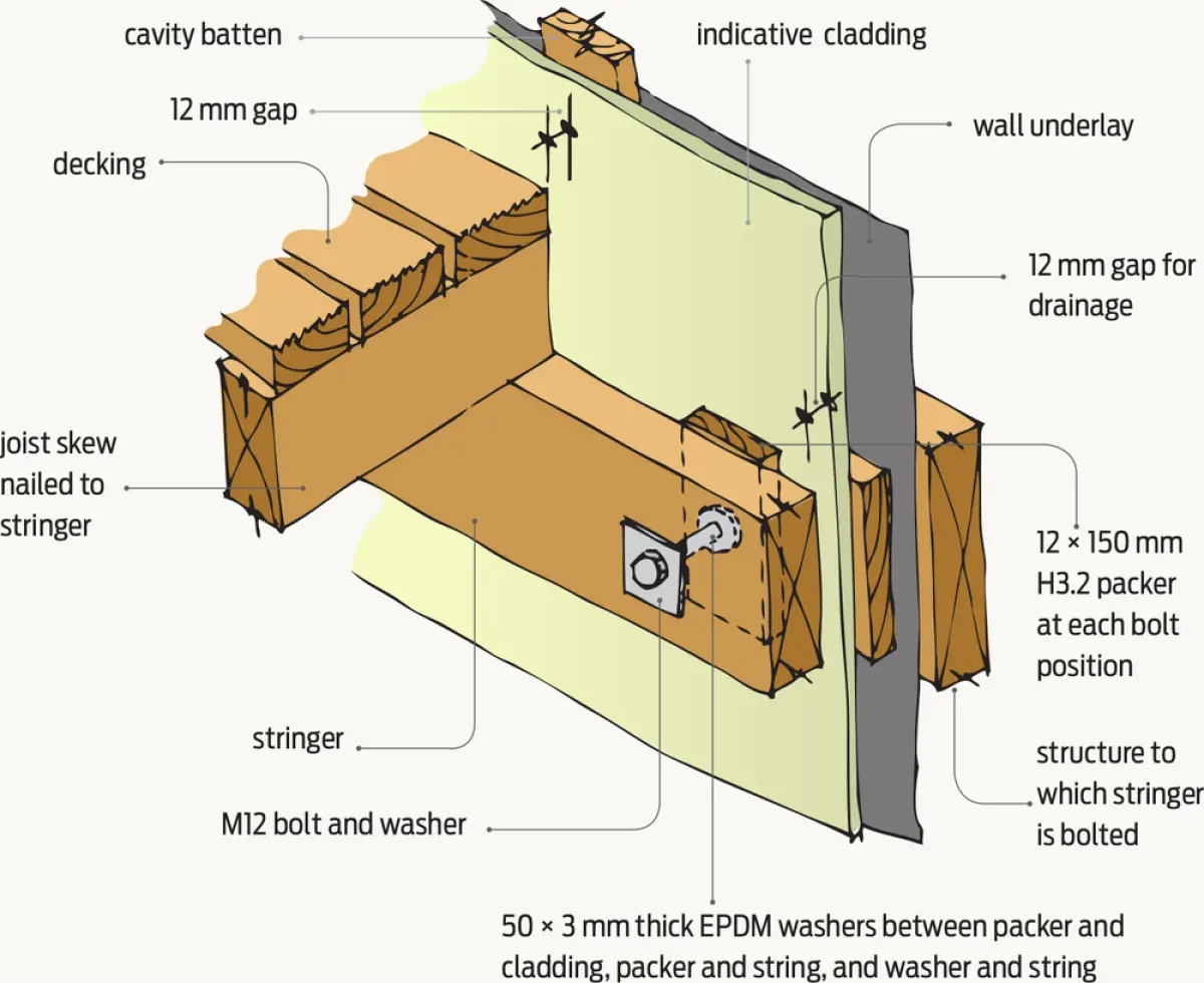
Step 7: String fixing through cladding
When installing slatted timber decking, leave:
- a 12 mm minimum gap between the stringer and the decking
- a 12 mm minimum gap between the cladding and the decking for drainage (E2/AS1 paragraph 7.1.1) – see Figures 3 and 4
- a 3–6 mm gap between decking timbers lengthways (NZS 3604 recommends using a 100 × 3.75 mm nail as a spacer) to allow timber movement due to moisture and temperature changes and for water to drain.