


There have been many reported cases during windstorms where roofs have peeled off after damage initiating at the gable verges.
Unfortunately, the provisions for gable verge outriggers in NZS 3604:2011 Timber-framed buildings are confusing and incomplete.
Designing overhanging verges
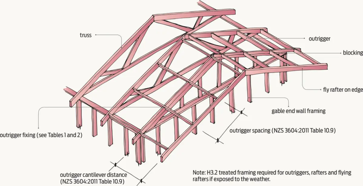
The 2011 revision of NZS 3604 allowed an increase in the maximum verge cantilever distance from 600 mm to 750 mm and also introduced an additional higher wind zone EH. It’s therefore important that the industry is clear on the limits and fixing requirements for cantilever verges (see Figure 1).
Overhanging verges may be formed by cantilevering the purlins or, more commonly, by outrigger framing. Clearly, it is beyond the scope of NZS 3604:2011 to increase the overhang by combining both purlin cantilevers plus outriggers.
Points to note
When reading NZS 3604:2011, there are some clarifications and corrections for clause 10.2.1.15.2 Purlins, and 10.2.1.15.3 Outriggers:
- Fixings for purlins on the flat are given in Table 10.10. These are also suitable for the cantilever distances given in 10.2.1.15.2(a).
- The reference in clause 10.2.1.15.2(b) to Table 10.8(a) is incorrect. Table 10.9 (see Table 1) could be used for purlins on edge when cantilevered.
- The reference in clause 10.2.1.15.3 to Figure 10.16(A) should be to Figure 10.16(B).
- The reference in clause 10.2.1.15.3(a) to Figure 10.17 is spurious and can be ignored.
- Clause 10.2.1.15.3(b) requires outrigger fixings to be determined from Tables 10.10 or 10.11, although neither is oriented to outrigger requirements, making interpretation difficult.
BRANZ tables clarify
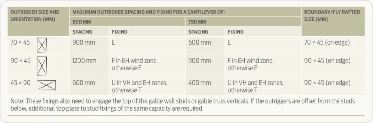
For simplicity and to avoid errors, readers can use Tables 1 and 2, which have been adapted from the outrigger Table 10.9 in NZS 3604:2011.
The backspan of outriggers is the distance to the first truss or rafter. A minimum of 600 mm has been assumed for the fixings in Table 1.
| FIXING TYPE | DESCRIPTION | ALTERNATIVE FIXING CAPACITY (KN) |
|---|---|---|
| E | 2/90 × 3.15 mm skew nails + 2 wire dogs | 4.7 |
| F | 2/90 × 3.15 mm skew nails + strap fixing (see Figure 10.6) | 7.0 |
| T | 1/10 g self-drilling screw, 80 mm long | 2.4 |
| U | 1/14 g self-drilling Type 17 screw, 100 mm long | 5.5 |