



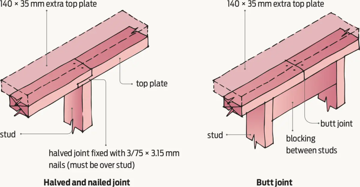
Top plates of walls that contain no bracing elements in line or at right angles (see Figure 1) require:
- a halved and nailed joint, or
- a butted and blocked joint, or
- an alternative fixing with a 3 kN capacity in compression or tension.
Walls with bracing – in-line connections
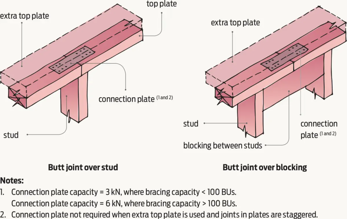
For the top plates of walls that contain bracing elements (see Figure 2), the connection capacity in tension and compression along the plate is based on the highest rated individual bracing element in the wall, specifically:
- walls with bracing capacity up to 100 BUs require a 3 kN capacity connection
- walls that exceed 100 BUs require a 6 kN capacity connection
- walls that have ceiling diaphragms attached to them require a 6 kN capacity connection.
Where double top plates are used and the joints in the additional top plates do not align with the first top plate, then halved, blocked or 6 kN connectors are not required.
Walls with bracing – right-angle connections
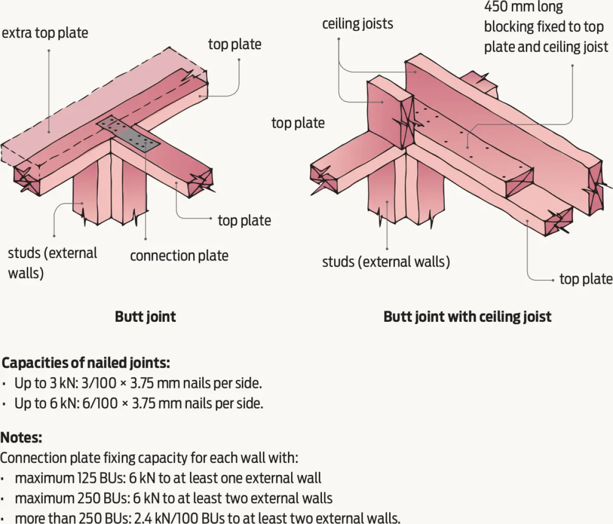
Connections of external walls to others at right angles can be direct or through other framing members (such as truss bottom chords, ceiling joists or ceiling battens) that are in the line of the braced wall (see Figure 3). For each wall, the required connection capacities in tension and compression relate to the wall’s bracing capacity.
Where this:
- does not exceed 125 BUs, use a 6 kN connection to one external wall
- does not exceed 250 BUs, use a 6 kN connection to two external walls
- exceeds 250 BUs, connections that are not less than 2.4 kN per 100 BUs to two external walls are required.
Worked example
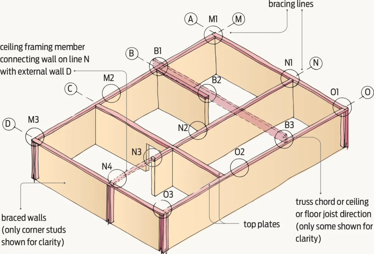
Using Figure 4, we can work through these various options.
In-line connections in top plates
For the in-line connections at M2, N2, N3 and O2 in Figure 4, if total bracing in lines M, N or O:
- does not exceed 100 BUs, use 3 kN connections
- exceeds 100 BUs, use 6 kN fixing.
Where double top plates are used and joints in the top plates are staggered, neither of these are needed.
Right-angle connections in top plates
For right-angle connections in Figure 4 at M1 and O1, if the wall in line A has:
- up to 250 BUs, a 6 kN connection is required at each end of line A
- over 250 BUs, the corner connections must have a capacity of at least 2.4 kN per 100 BUs.
For connections at N1 and N4 in Figure 4, where bracing in line N:
- does not exceed 125 BUs, at least one 6 kN fixing to an external wall must be used
- does not exceed 250 BUs, use a 6 kN fixing to each end at both external walls
- exceeds 250 BUs, use a fixing capacity of 2.4 kN per 100 BUs at both external walls.
Connection of line B to external walls on M and O depends on the bracing in the wall. Where wall B:
- has no bracing, use a 3 kN connection or options of halved or blocked joints as above
- bracing does not exceed 125 BUs, use a 6 kN connection at B1
- bracing over 125 BUs and up to 250 BUs, a 6 kN connection will be required at B1 and it will need to be connected to external wall O with a bottom chord of a truss or a ceiling joist (B2 and B3)
- bracing that exceeds 250 BUs, 2.4 kN connections per 100 BUs would be required at B1 (as above), and it will need to be connected to external wall O with a bottom chord of a truss or a ceiling joist (B2 and B3).
Top plates requiring lateral support
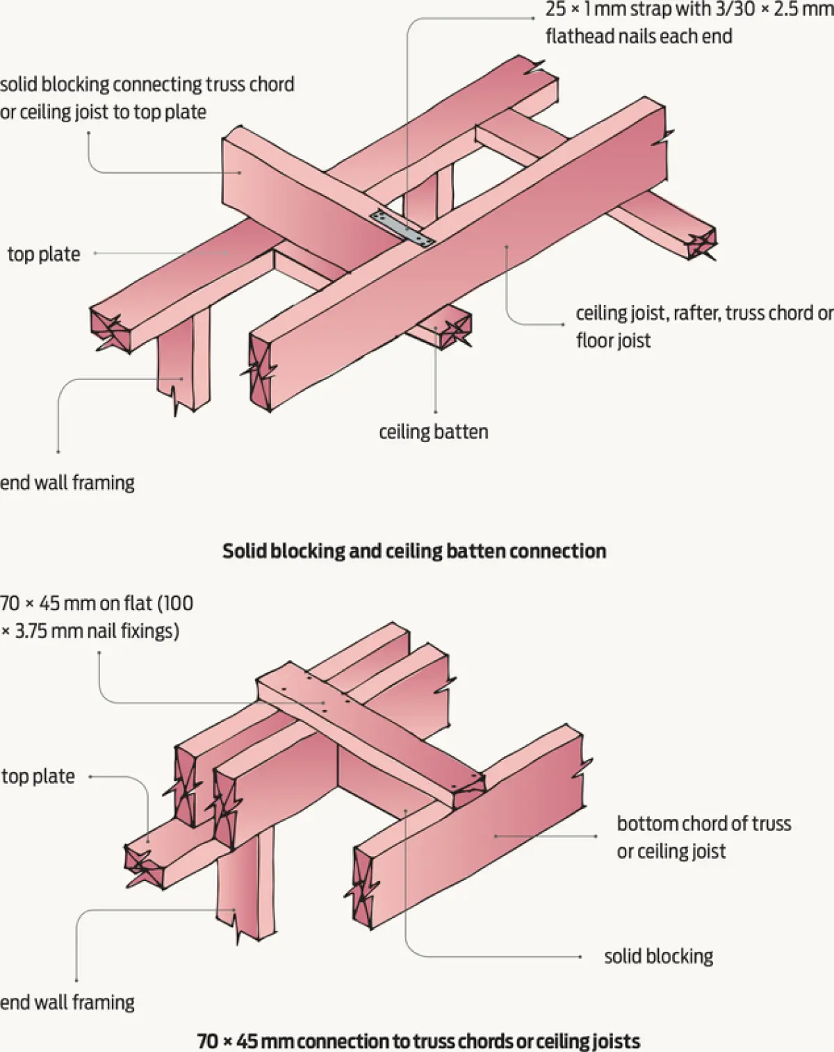
If the ceiling has a density of less than 600 kg/m³ (for example, softboard), the top plates require lateral support. This can be provided by ceiling framing members spaced at not greater than 2.5 m or 70 × 45 mm connecting members (see Figure 5).