

For single-storey buildings, there is no limit on the total, area allowed for a concrete slab-on-ground floor under the amendments to NZS 3604:1999 Timber framed buildings (see Clause 1.1.2 (n)). However, if a concrete slab-on-ground floor exceeds 24 m in any direction, the area must be broken up by free joints. This ensures that no individual slab exceeds 24 × 24 m (or, when using 868 mesh reinforcement, 12 × 12 m).
| Reinforcing type | Max. slab size | Max, control joint spacing | Max. length-to-width ratio of bay | max. length × min. width |
|---|---|---|---|---|
| 665 mesh | 24 × 24 m | 6 m | 2:1 | 6 × 3 m |
| 668 mesh | 12 × 12 m | 5 m(1) | 1.75:1(1) | 5 × 2.85 m |
| Fibre | 24 × 24 m | 4 m | 1.5:1 | 4 × 2.7 m |
| Nil | 24 × 24 m | 3 m(2) | 1.3:1 | 3 × 2.3 m |
Notes: (1) BRANZ recommendation.
(2) In an un-reinforced slab, a ‘shrinkage control joint’ will act as a ‘free joint’ after cracking has occurred. So for practical purposes, free joints may occur at 3 m spacings.
Floor area and free joints
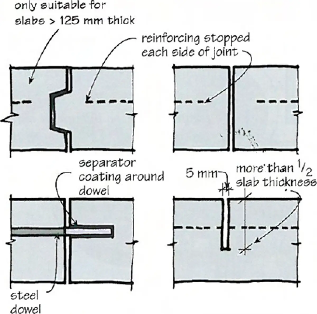
A free joint is defined in NZS 3604 as ‘a construction joint that has no reinforcement passing through it and the vertical faces of the joint must not be to bonded contact with each other’. If they are formed by separate pours, NZS 3604 requires that the concrete on one side of a free joint be allowed to harden for 16 hours before new concrete can be placed on the other side of the joint (as for any ‘construction joint’).
BRANZ suggests that a practical alternate way of forming a free joint is to saw-cut the concrete to one half of the thickness of the floor. The saw-cut must be deep enough to ensure any reinforcing passing through the joint is cut through when the slab is cut. In summer, this should be done no later than 24 hours after pouring. In winter, It should be done within 48 hours. This method allows the placing of concrete for a complete floor area in one operation. See Figure 1 for other methods of forming free joints.
Reinforcement & shrinkage control joints
Shrinkage control joints should be formed within 24–28 hours after pouring to prevent uncontrolled random cracking as shrinkage occurs.
A shrinkage control joint is defined in NZS 3804 as ‘a line along which the horizontal strength of a slab is deliberately reduced so that any shrinkage in the slab will result in a crack forming along that line’.
Section 7.5 of NZS 3604 sets out the maximum spacing for shrinkage control joints in slabs with different levels of reinforcing. It also sets out limits for the length-to-width ratio of the bays between control or free joints and the edge of the floor (see Table 1), (Note that bays are referred to in MZS 3604 as ‘concrete slab bays’.)
Examples 1 and 2 on page 24 show how Table 1 Is applied. The designer should show the location of shrinkage control joints on the floor plan. This is especially important where floor finishes art affected by concrete floor shrinkage.
Example 1: Un-reinforced slab-on-ground
For un-reinforced concrete floors on ground, a shrinkage control joint effectively becomes a free joint, limiting the slab size to the size of the bays.
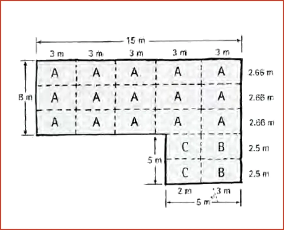
| Bay | Min. width1 | Max. and min. bay sizes | Actual size | Within NZS 3604 bay size? |
|---|---|---|---|---|
| A | 2.3 m | max. 3 × 3 m min. 3 × 2.3 m |
3 × 2.66 m |
yes |
| B | 2.3 m | max. 3 × 3 m min. 3 × 2.3 m |
3 × 2.5 m |
yes |
| C | 1.9 m | max. 2.5 × 2.5 min. 2.5 × 1.9 m |
2.5 × 2 m |
yes |
Note: 1 Min.width = max.length + length-to-widthratio.
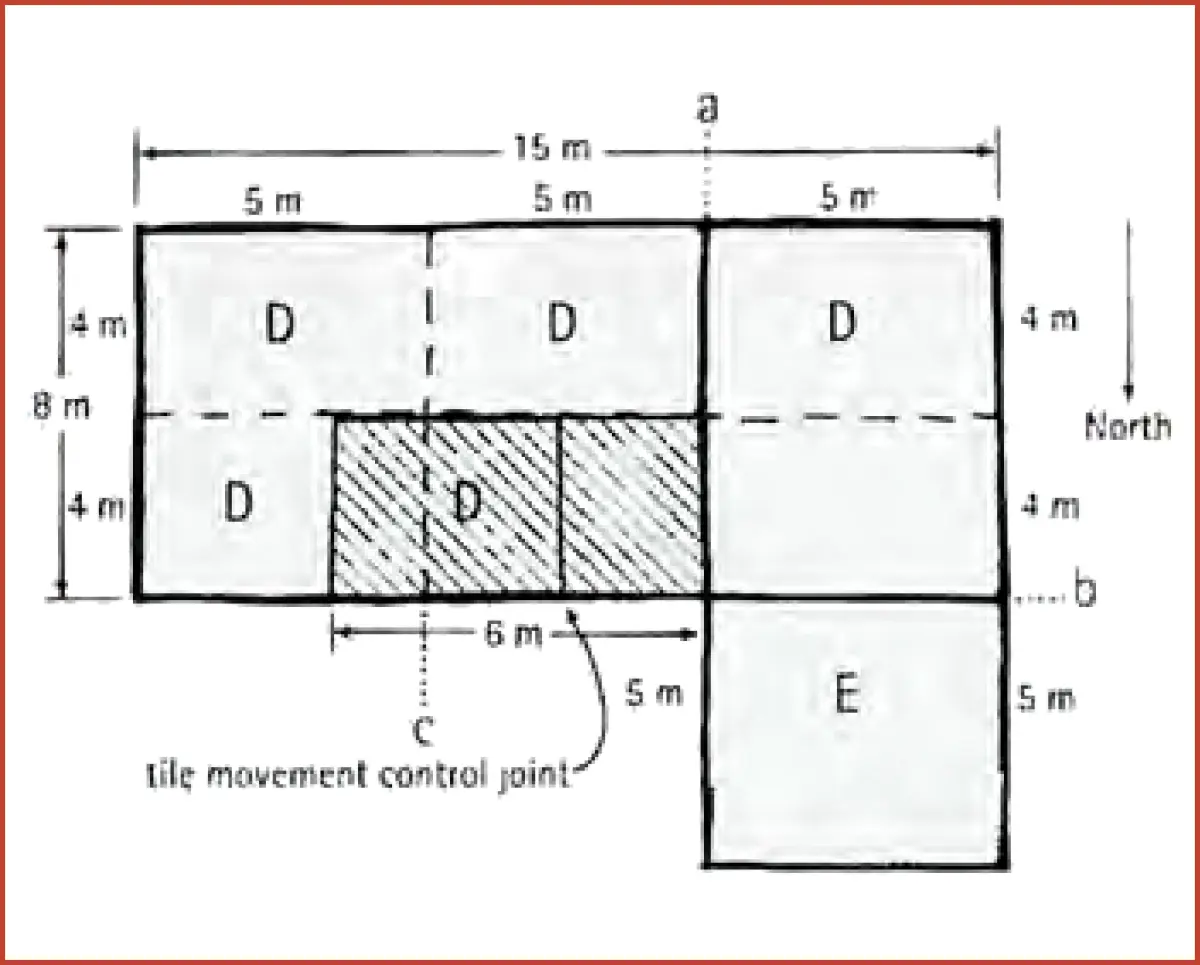
Example 2: Reinforced slab-on-ground
For a slab-on-ground floor reinforced with 668 mesh, the maximum permitted slab area is 12 × 12 m. When, this is exceeded, you must introduce free joints at lints ‘a’ and ‘b’. No reinforcing is to pass through lines ‘a’ and ‘b’. Reinforcing can be stopped at each side of these joints or cut through (if the free joint is formed by saw cutting).
| Bay | Min. width1 | Max. and min. bay sizes | Actual size | Within NZS 3804 bay size? |
|---|---|---|---|---|
| D | 2.85 m | max. 5 × 5 m min. 5 × 2.85 m |
5 × 4 m |
yes |
| E | 2.85 m | max. 5 × 5 m min. 5 × 2.85 m |
5 × 5 m |
yes |
Note: 1Min.width = max.length +length-to-widthratio.
For instance, ceramic tiles should not be laid across control joints because the tiles are very likely to crack there. Movement control joints in the tiling must coincide with shrinkage control joints in the concrete floor. Even where vinyl coverings are used, it is very difficult to mask a shrinkage control joint. So, if possible, hide the joints under internal walls.
Floor tiling
In Example 2, the hatched area is to be covered by 300 × 300 × 8 mm ceramic tiles. This area has a 2.7-m-wide, north-facing window – sunshine will heat the floor, so thermal expansion of the tiles needs to he allowed for (via additional movement joints) to prevent cracking. Movement joints in tiling should be spaced at a maximum distance of 4.5 m.
The width of the floor bays (D) is 4 m minus the thickness of the exterior wall, so we don’t need a movement joint to divide the width in that direction. Each floor bay is 5 m long, so the tiles will need a movement control joint. The best place is half-way along the bay. (The last row of tiles near line ‘a’ may need to be cut.)
To prevent laying individual tiles across the shrinkage-control joint of the slab, the tile set-out in our example should start from the control joint at line ‘c’ (see Example 2).
Space must also be allowed during tile set-out for movement joints around the perimeter of the floor where the tiling finishes against the walls.
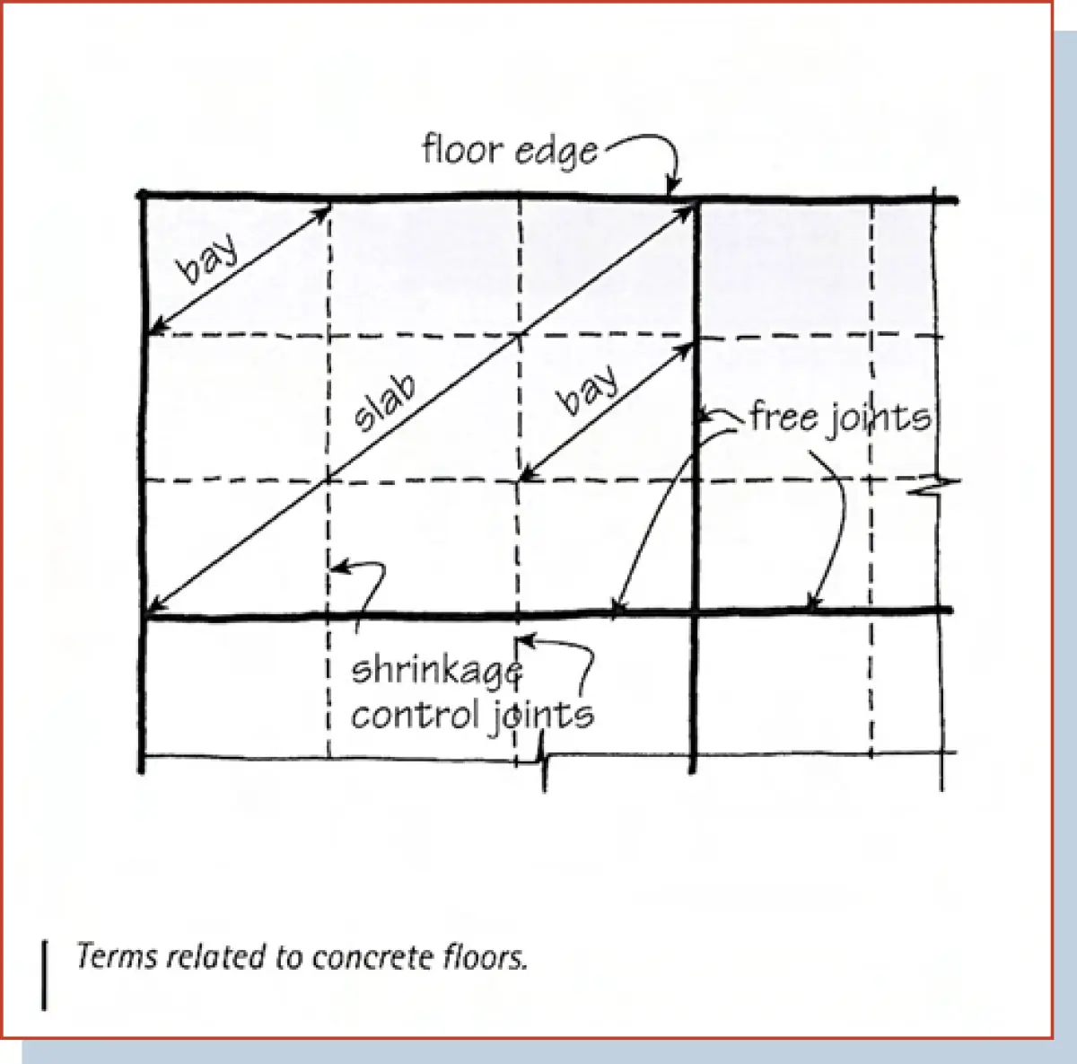
Definitions of concrete floor terms
The terms used in NZS 3604 can be confusing, hence the terms used in the preceding article are defined as follows.
Floor
NZS 3604 section 1.1.2(n)(i) states ‘the plan floor area shall be unlimited for one and two storey buildings where all storeys are of timber frame’. it seems reasonable to call the total area of concrete a ‘floor’ or an ‘on-ground concrete floor’.
Slab
Several definitions of ‘slab’ in the standard refer to a section of concrete divided by (a) construction and control joints, or (b) free joints, or (c) construction joints, or (d) shrinkage control joints. The BRANZ interpretation of a ‘slab’ is an area of concrete floor bordered by the floor edge and/or free joints (i.e. joints with no continuous reinforcing passing through them).
Bay
The standard refers to a concrete slab ‘bay’ as bordered by construction or control joints. This definition can be improved by referring to ‘shrinkage control joints’ (i.e. a joint formed, with reinforcing continuous through it). The BRANZ interpretation of a ‘bay’ is therefore an area of concrete bordered by shrinkage control joints, the slab edge and/or a free joint.