


Acceptable Solution E2/AS1 in New Zealand Building Code clause E2 External moisture includes the performance requirement in E2.3.5 that ‘Concealed spaces and cavities in buildings must be constructed in a way that prevents external moisture being accumulated or transferred and causing condensation, fungal growth or the degradation of building elements’.
Restricting moist airflow
Specific requirements for cavities in E2/AS1 clause 9.1.7.4(c) include that a drained cavity, where required, shall restrict air movement between the drained cavity and:
- floor, wall and roof framing
- attic roof space
- subfloor space.
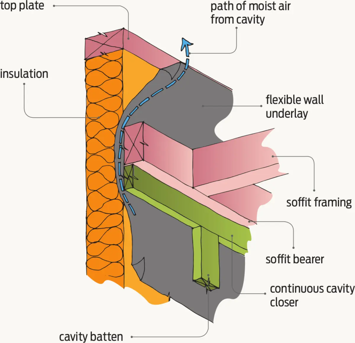
Moist air, if present in roof spaces, may condense on cold nights and drip on to insulation, compromising the R-value and wetting it, which can then create rust or rot problems in ceiling or roof members.
Correctly detailing the soffit to wall framing junction will help prevent moist air from cavities getting into the ceiling where a flexible wall underlay is used.
Timber framing
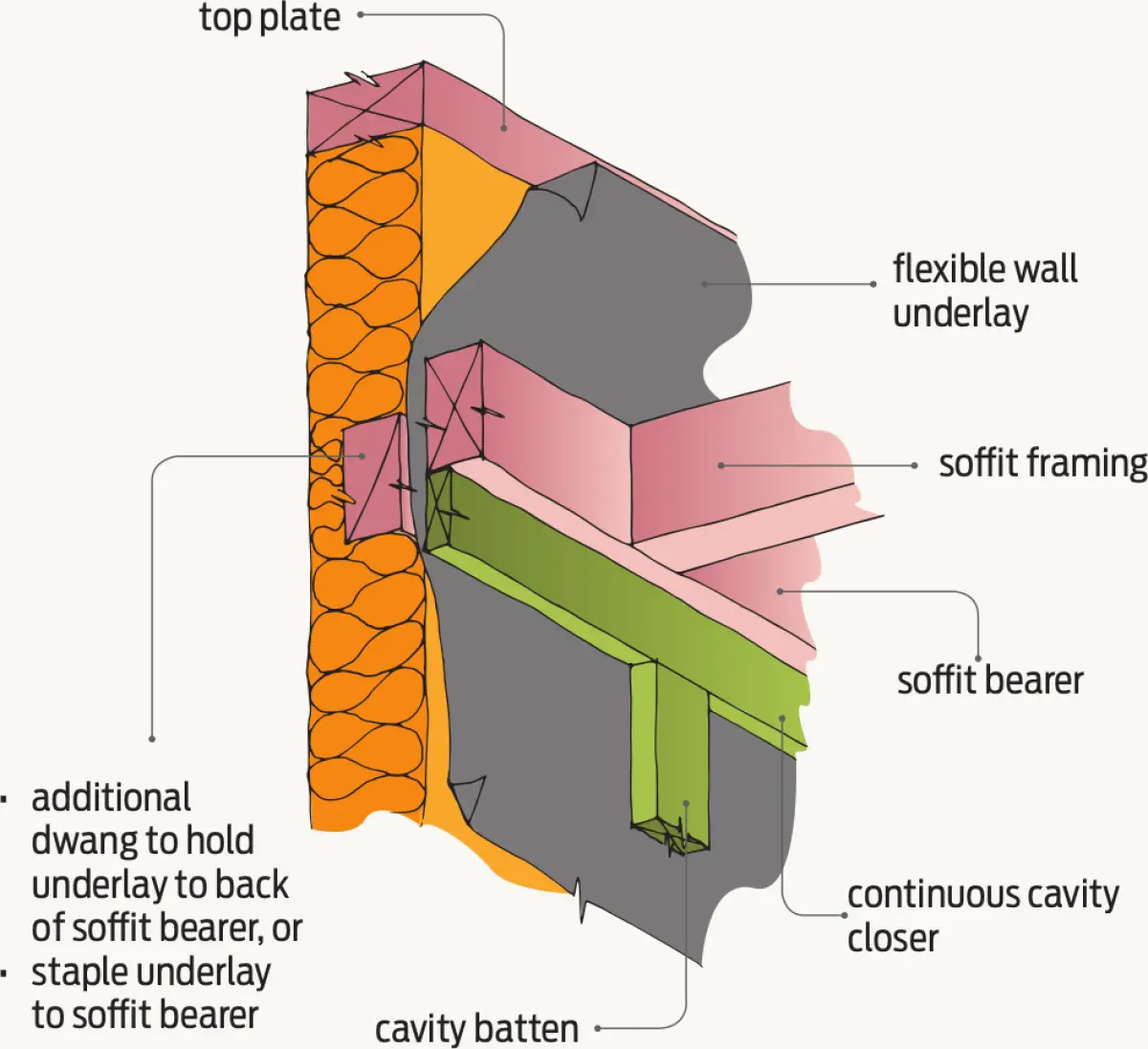
For timber frames, the flexible wall underlay may billow or bulge away from the soffit bearer, allowing cavity air into the roof space (see Figure 1). This can be overcome by:
- ensuring insulation is installed for the full framing depth
- adding an additional batten fixed to the soffit bearer from inside
- fixing the flexible wall underlay to the soffit bearer from inside to hold the wall underlay tight to the back of the soffit bearer.
Where vertical weatherboards or sheet claddings are used, there will be a row of dwangs behind the top cavity closing batten to fix the cladding to (see Figure 2). The flexible wall underlay will be sandwiched tight so nothing extra is required.
Steel framing
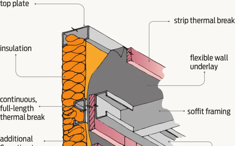
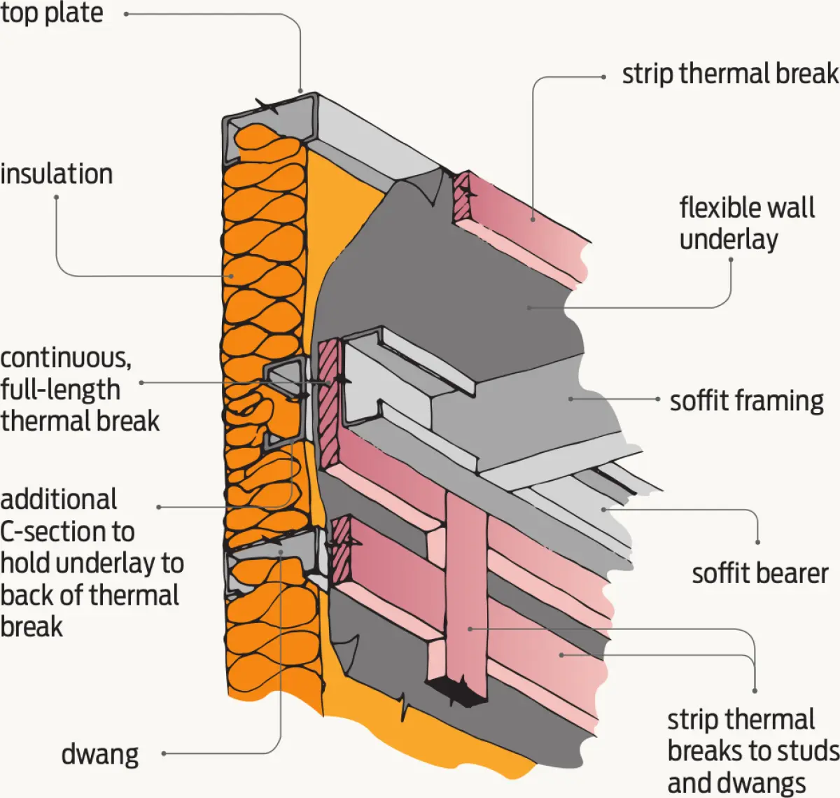
The same applies to steel framing that has strips of thermal break applied to the steel. Care is required where thermal breaks are attached to the frames. To close off the cavity to the roof space, an additional full depth C-section will be required behind the soffit runner when the runner is below the top plate (see Figure 3).
The best option for steel framing is to use a thermal break sheet material over the whole frame. Cavity battens, where required, are then installed over the thermal break and wall underlay, and a closing C-section is installed directly under or behind the soffit line or fix the sheet material from the inside to the soffit runner. This will then close off the cavity to the roof space.