


Bracing lines are imaginary lines running along or across the full length or width of a timber-framed building. They have no physical significance but are required to control the positioning of bracing elements.
Laying out bracing lines
There are a few rules for the layout of bracing lines to ensure good seismic performance:
- They must run in two orthogonal directions, generally aligned to match the wall layout – NZS 3604:2011 Timber-framed buildings says they must be parallel to the external walls.
- They should be as evenly spaced as practical. Generally, use more bracing lines rather than fewer, as this makes the distribution rules easier to apply.
- Where two walls are parallel to one another and:
- up to 2 m apart, consider placing a single bracing line between them – bracing elements in both walls contribute to the total of the line
- more than 2 m apart, insert an extra bracing line – the number of brace elements required won’t be affected as there is no change to the demand, and which wall or line they go in is merely a matter of convenience.
- Timber-framed floor and ceiling construction with standard or typical detailing can transfer lateral loads between bracing lines spaced up to 6 m, or 7.5 m with dragon ties (NZS 3604:2011). A structural diaphragm is required for spacings wider than this.
- Bracing elements can be located anywhere within the bracing line. This is helpful with door openings or an open room space. A continuous top plate can distribute the demand within reason.
Examples help explain the concept
By understanding the bracing line concept, designers have more freedom with room sizes.
In Figure 1, the large hatched room appears to require a structural ceiling diaphragm because of its size. However, there is a suitable arrangement of bracing lines across and along the building. Provided the distribution rules of NZS 3604:2011 are followed and enough bracing elements are located in each wall, this plan will be adequately braced. Note that the top plates of walls containing bracing elements must be continuous to the external walls (clause 8.7.3.4 of NZS 3604:2011).
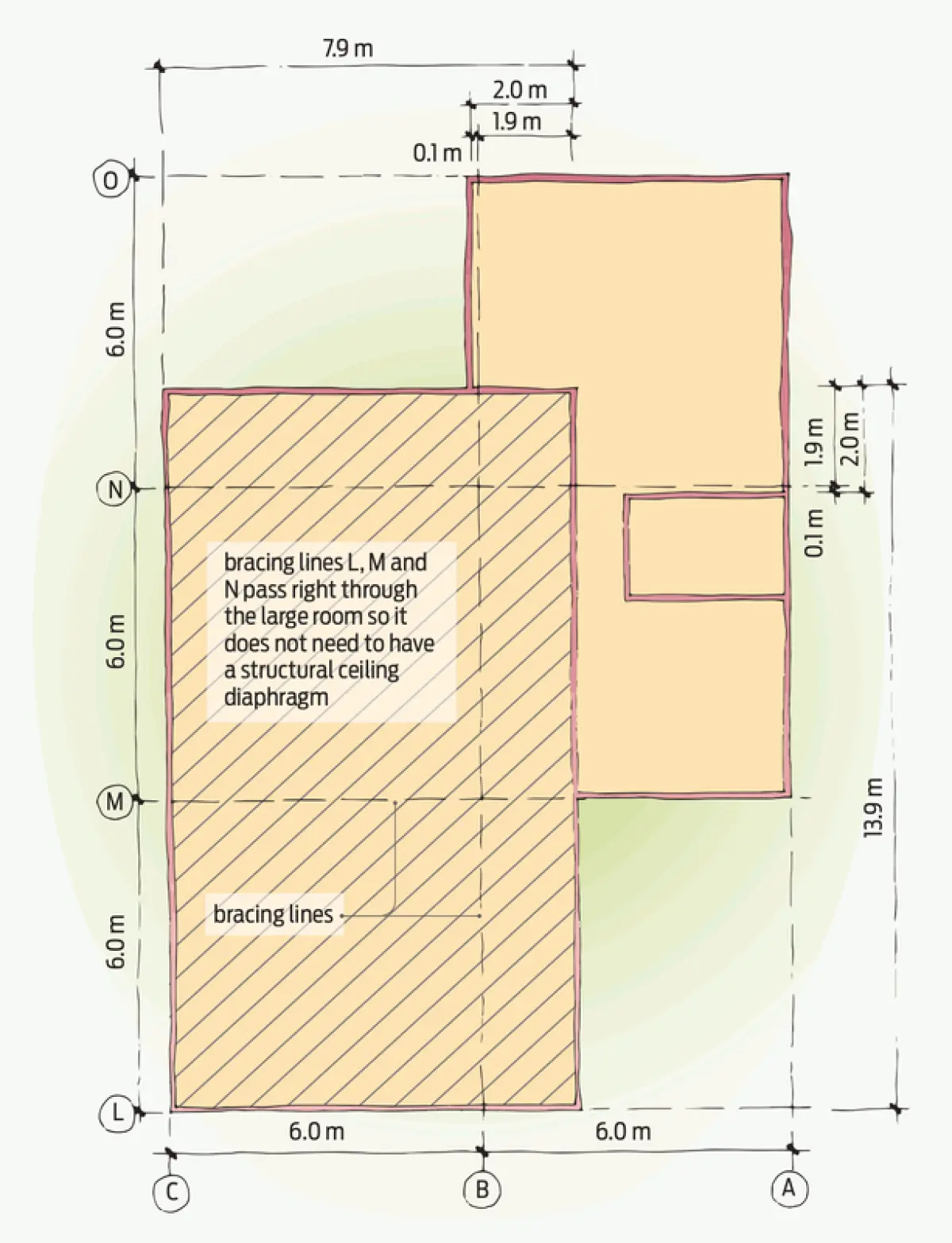
Figure 2 shows another situation often asked about. The exterior portion of wall on bracing line B has a large door and can’t provide the required external wall demand of 15 × length within its own length. However, this requirement can be placed anywhere on the bracing line. The shaded interior portion of the wall would comply provided the top plate is continuous to the external walls.
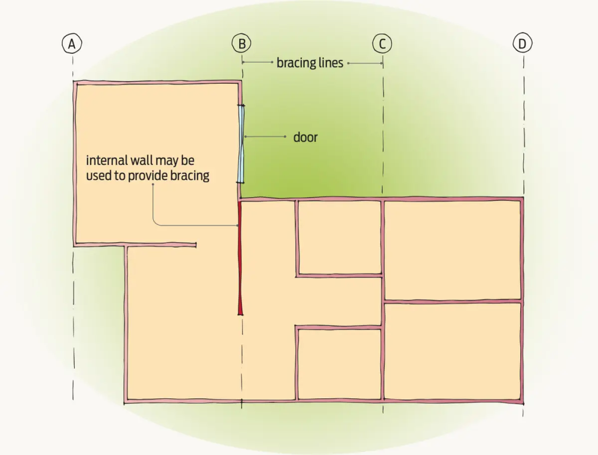
Although clause 5.4.3 of NZS 3604:2011 states that bracing elements shall be located as close as possible to external corners, this is often prevented by the location of walls suitable for bracing. While this is the ideal, the intent of this clause is attained provided top plate continuity is achieved. Again, the distribution rules of NZS 3604:2011 must be complied with.
Diaphragm transfers bracing loads
Timber-framed buildings in New Zealand are constructed as ‘platform framing’, which means we build one level at a time. We take the same approach with bracing design, considering each level separately, with no requirement to align bracing walls in each level (clause 5.4.3).
When bracing elements in different storeys don’t line up, a load path is required to transfer the bracing loads from the upper level down to the lower level bracing. This load path may be a floor or a normal flat plasterboard ceiling acting as a diaphragm.
A diaphragm is a horizontal (or near horizontal) bracing element that transfers forces between vertical bracing elements. The diaphragm does not count in the bracing design for either level but is needed to connect the two levels together.
Structural diaphragm if >6 m apart
When bracing lines are spaced more than 6 m apart, a specially detailed structural diaphragm is required, according to NZS 3604:2011.
Diaphragms must be continuous
To function correctly, a structural diaphragm must be continuous over its whole area.
If the ceiling in the large room (Figure 1) was at a higher level than the rest of the building, specific engineering design would be required because of the loss of continuity.
Steps in floors are a break in this continuity. NZS 3604:2011 requires that steps greater than 100 mm are effectively treated as separate diaphragms, with a bracing wall required below the discontinuity (clause 5.1.5).
Bends in ceilings (for example, ridges, hips, valleys, coved ceilings) are another type of discontinuity. NZS 3604:2011 doesn’t provide any guidance or details in this area, so BRANZ recommends that these are not used for diaphragms.
Technical literature that provides continuity details at folds and edges of ceiling diaphragms should be used rather than the provisions of NZS 3604:2011.