


At a glance
- Window head flashings can be tricky to get right.
- E2/AS1 gives guidance around minimum dimensions.
- BRANZ research has indicated what approach gives the best leak resistance.
The need for guidance on window flashings backs up the findings of a BRANZ research project a few years ago involving visits to over 200 houses under construction. Problems with head flashings were found in almost 40% of the homes visited.
The issues found with head flashings included:
- no stop-ends or upturns
- upturns too small
- flashings too short to cover the window frame at the ends
- inadequate slope to flashing surface
- inadequate gap between flashing and cladding
- flashing in two pieces with a poor or missing junction seal.
What should happen
If you are using E2/AS1 to demonstrate Building Code compliance, you will install a metal head flashing with a minimum 15° slope against the wall underlay and over the window frame to provide 10 mm cover to the face of the window frame (Figure 1). The flashing should be in a single piece that fully reaches both ends of the frame. Stop-ends must be formed at each end to prevent water running behind the cladding.
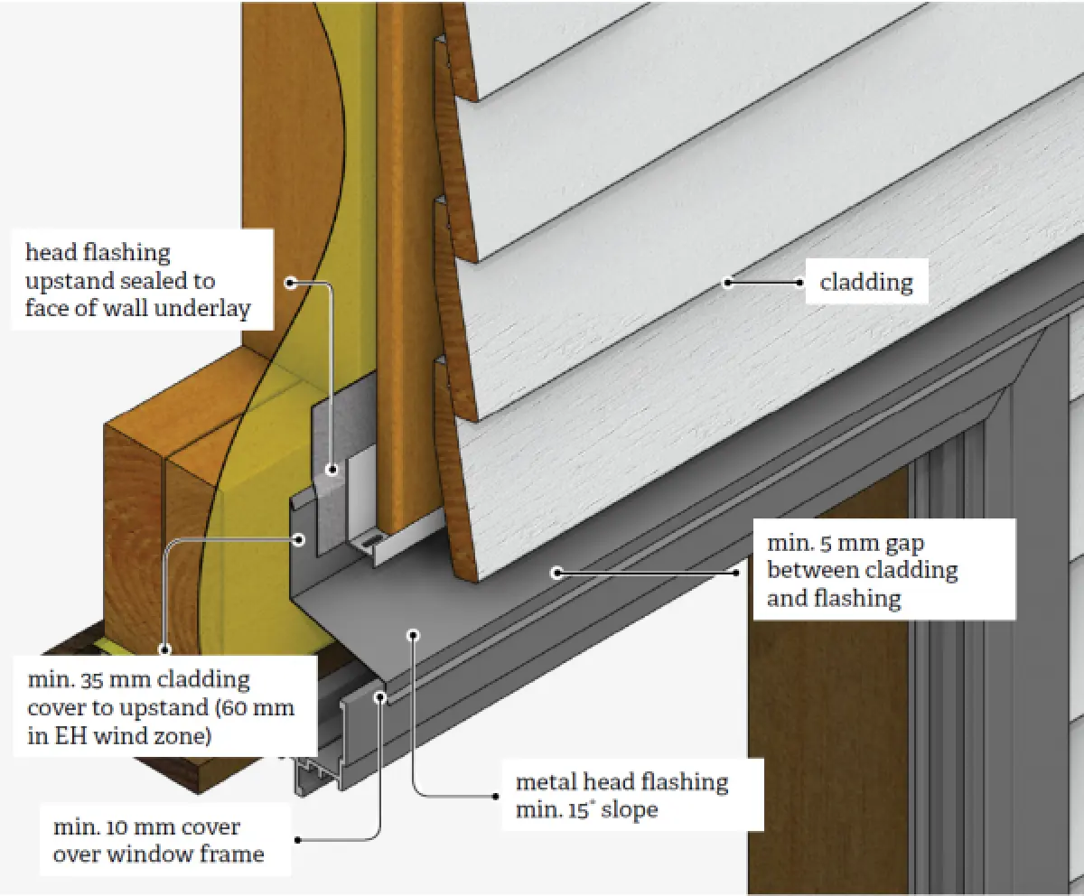
A 5 mm minimum drainage and venti-lation gap between the top surface of the sloped flashing and the bottom of the cladding above it lets water drain from the assembly and lets in air to provide drying.
The head flashing upstand must be sealed to the face of the wall underlay with flexible flashing tape, or an extra layer of wall underlay must be dropped from above to create a gravity drainage path out over the flashing. The total upstand must be 40 mm minimum. The lap under the cladding must be a minimum 35 mm or 60 mm in an extra high wind zone.
Key requirements for head flashings are in Acceptable Solution E2/AS1 4th edition, Table 4.5.1.1 and Figure 9.1.10.1. In addition the Acceptable Solution also requires:
- with direct-fixed claddings, a 50 mm sealant bead between the cladding and each end of the flashing
- in cavity construction, 10 mm turn-ups acting as stop-ends, finishing at the inside face of the cladding and not passing through it, and ventilation of the cavity with use of a cavity base closure
- in very high and extra high wind zones, there must be sealant between the underside of the head flashing and the top of the window head flange
- sloped heads must have specifically designed kick-out flashings at the bottom edges of head flashings.
A tight fit is best
BRANZ in-lab research assembled a window head joint with the capacity to adjust the position of the upper cladding in relation to the window head flashing. This allowed for some variations in joint dimensions, in particular, the gap between cladding and flashing.
The tests with water spray found that head flashings were more leak resistant when the upstand fitted tightly against the cavity closure. It also found that window head flashings handle run-off better where there is a greater clearance between clad-ding and flashing.
Several prefabricated head flashings carry a BRANZ Appraisal. These are avail-able in galvanised steel, factory-coated steel, stainless steel and aluminium. Table C1.1.1A in E2/AS1 4th edition gives guidance for the appropriate selection depending on exposure zone and whether the flashing is exposed or sheltered, as per section 4 of NZS 3604:2011 Timber-framed buildings.
MBIE gives practical guidance on selection and installation outside of E2/AS1:
- Builders and window suppliers should use the ‘nearest fit’ size of an extruded head flashing to suit each job.
- If a head flashing is so tight that it is difficult to engage the window frame, it will risk distorting the head flashing and
damaging the window frame coatings. A gap for fitting tolerance is required. - Either a kick-out along the bottom edge of the flashing and/or an overhang of the flashing is necessary to deflect water off the joint.
- When installing the head flashing, make sure it is in contact with the top edge of the window flange to ensure the maximum overlap dimension of the downturn part of the head flashing and act as an effective air seal to prevent air/water intrusion through the joint.
- An effective air seal for lower wind zones can be achieved by close contact of the flashing onto the top edge of the flange. For higher wind zones, a sealant or compressed foam seal in the gap is more effective. As noted above, E2/AS1 requires a sealant bead along this joint in very high and extra high wind zones.
BRANZ recommends homeowners clean the visible parts of window head flashings once a year with a soft brush, warm water and detergent.
For more: View E2/AS1 4th edition